Sliding mode control
PID control is the gold standard for most moving machines, and quite adequate in most applications that require closed-loop control. However, it's vulnerable to disturbances, and tuning can be tedious. For these reasons, some industrial drives go beyond traditional PID structures and servo algorithms for position control — with sliding mode algorithms that increase stability over a wider range of conditions, to make tuning easier for design engineers.
Sliding mode control was first defined and expanded in the 1950s by Russian mathematicians. Since then, it has been developed into a general design method. Though it's still relatively uncommon in industrial applications, sliding mode control has been applied in some cutting-edge positioning machines, and promises to benefit more motion systems in the future. In fact, the algorithms are particularly well suited to embedded control designs with limited resources and budgets.
Sliding-mode theory
Sliding-mode tuning is robust in that it can handle large inertia variation — so then only a few parameters require adjustment to optimize system response. The control design process is divided into two stages:
-
Design an asymptotically stable hyperplane that contains the destination of the control — for which any points on the plane automatically converge to the destination. In short, the hyperplane is a mathematical set of distinct machine conditions.
-
Design an enforcing control so that the system state starting from anywhere in the state space is forced to reach the hyperplane.
For second-order motor control:
Where θ and ω = Motor position and velocity, and their dots denote derivatives with respect to time
Te = Motor torque
bp = Motor damping/friction coefficient
ΔT = Summation of load torque and disturbance torque acting on the motor shaft.
Assuming that motor motion follows a target trajectory:
Where θd and ωd = Target motor position and velocity
f(t) = Time-dependent function describing target motor acceleration
Defining e1 = θd - θ and e2 = ωd - ω, we then subtract our first equation from the second to get:
Based on this equation, we define the target hyperplane:
After the sliding mode is designed, we can design an enforcing control:
Where Ksliding = Constant to be selected
ε = A small number
SIGN (S) = Sign function of S
We must select a proper Ksliding to make the system asymptotically stable. This can be achieved by selecting an appropriate Lyapunov function based on specific application conditions.
Page 2 of 2
Practical application
From our last equation (defining enforcing control) we see that the discontinuous term åSIGN(s) is used in sliding mode control law to handle the modeling of imprecision and disturbances.
In this case, the control law must be discontinuous across the sliding surface to drive the system state back and stay on the sliding surface.
In practice, unlike the ideal condition discussed above, the discontinuous crossing — so-called switching — takes time to finish, so more time is needed for the digital control system due to the sampling.
In addition, the value of s is not known with infinite precision. All of those imperfections make the system continuously jump between two sides of the sliding surface and thus it is difficult to converge to the desired state. This condition can lead to chatter.
In general, chatter is highly undesirable, because it involves high energy and extremely high control activity. Furthermore, it may excite high-frequency dynamics, which are neglected in models.
For an electrical motor, the direct implementation of switching control law may be acceptable and chatter avoided as long as the frequency of actuating the signal is beyond the frequency range of the relevant unmodeled dynamics and if the sampling rate is high enough. This is because the electrical motor coil is a large induction load, for which performance is like that of a low-pass filter.
In addition, a common solution to mitigating undesirable chatter is to set a looser switching condition in place of a strict one — for example, when S = 0. This can be achieved by widening the switching from a line S = 0 to a strip.
Comparison of algorithms
PID control is limited, as it depends on a plant model, so is sensitive to real-world parameter variations and disturbances such as motor and load inertia changes. In contrast, sliding-mode algorithms have a much simpler control structure. Unlike other advanced servo algorithms (such as pole placement with a Kalman filter) sliding mode control structure is simpler. Its performance and ease of use are comparable to that of competitive technologies.
Another advantage of sliding mode control is that the majority of applications need only manipulate one parameter to achieve optimal performance making it easier to use.
The sliding mode gain Ks is the primary tuning parameter and is related to system inertia: If inertia is increasing, Ks should also increase. However, additional parameters are available to fine-tune even the toughest applications.
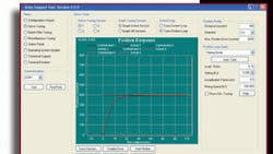
Parker Hannifin's Aries drives are capable of tuning and sliding-mode control. Results illustrated in this article were obtained with an Aries AR04-SE drive and MPP0923D servomotor. Visit parkermotion.com for details.
