20 Minute Tune-Up: Do not disturb
Most discussions about control systems center on command response. Commands are signals intentionally given to the controller to generate desired actions. Command response, a measure of how well the system follows those signals, is based on step response, bandwidth, rise time, and other parameters.
Disturbances, by contrast, are unwelcome inputs. One example is an instantaneous shaft torque applied to a stopped servomotor. Naturally the controller does its best to resist this torque, but it may not be able to hold the motor completely still. This brings up another important aspect about controllers, disturbance response, a measure of how well a system rejects disturbances. In this case, the ideal response is zero – the less the shaft moves, the better.
Disturbances occur in almost every motion-control application. Machinetool servos, for instance, are disturbed each time a cutting surface contacts a work piece. Similar reactions occur in printing machines when the printing plates contact the paper. Although no controller can completely counter all such disturbances, a well-tuned system can greatly mitigate their effect.
One way to achieve good disturbance response is to tune the system with high servo gains. Consider the response of a PI velocity controller (with low gains) subjected to a step disturbance. By simulation – with commanded speed set to zero – we see that shaft velocity is greatly perturbed by the disturbance. When the system is tuned up with higher gains, however, the path is less perturbed by the same disturbance.
Disturbance is often best understood on the basis of frequency. For example, gravity and friction are low-frequency disturbances. They act on a system at very low rates, giving the servo controller time to respond. On the other hand, disturbances from individual blades of a machine tool operate at high frequency. Here, the servo has little time to react. In fact, some disturbances have frequency content far above the range of the servo controller. In such cases, the system inertia must be relied on to attenuate disturbance.
Disturbance frequency provides many clues as to which servo gains will improve the system. For example, if the disturbance has only low-frequency content, higher integral gain will usually improve system response. This is the case with friction and gravity. For disturbances with high-frequency content, however, higher integral gains have little effect.
For as much as raising servo gain helps improve disturbance response, there is a point beyond which the system becomes unstable. If servo gains alone can’t compensate for disturbance, you may want to consider raising the total inertia. As discussed in last month’s column, when you raise total inertia, you can often raise loop gain proportionally.
Be cautious, however, when increasing total inertia. In order to avoid problems with mechanical resonance (see Tune up, November 1999), you should raise the load and motor inertia proportionally rather than just adding inertia to the load. Raising the motor inertia often implies using a larger motor, so motor cost may increase. Also, because it takes more power to accelerate a larger inertia, you may need a larger drive, which can also increase cost. If you can live with that, increasing total inertia is a time-tested way to improve disturbance response.
Although our discussion involves a velocity controller, the same principles extend to position loops. Consider a typical cascaded position/velocity loop, with a proportional position loop wrapped around a PI velocity loop. Because the position loop is in a lower frequency “zone” than the velocity loop, it can only reject the lowest frequency disturbances (the velocity loop must take care of high frequency disturbances).
PID position loops, which have no explicit velocity loop, are quite similar. Here the “D” gain rejects the highest frequency disturbances, the “P” gain rejects the middle frequencies, and the “I” gain helps only with the lowest frequency disturbances.
Raising gain
Want to learn more about disturbance response? Then log on to www.motionsystemdesign.com and download this month’s ModelQ simulation program. Launch the program, select “June 2000 Disturbance Response” from the combo box at top center and click “Run.”
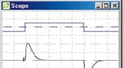
You should be looking at the system we referred to in the first example. A simulated 1-Nm square-wave torque disturbance is perturbing a PI-velocity controller. The gains of the PI controller are low, so the motor, which is commanded to move at zero speed, is greatly disturbed.
As you can see, when the gains are doubled (KVP goes from 0.72 to 1.4 and KVI from 100 to 200) the disturbance response is greatly reduced.
In the final example, the total inertia J is increased by a factor of four, from 0.002 to 0.008 kg m2. Then, according to last month’s discussion, KVP is also raised by a similar amount. (Note that this model assumes there are no problems with mechanical resonance.)
George Ellis is Senior Scientist at Kollmorgen Inc., Radford, Va. His new book, Control System Design Guide, (2nd Edition), was published last month by Academic Press. You can contact George at [email protected].
