Extending life with the right coupling
Even if a pump fails repeatedly, or if a motor's bearings continually fail before their rated life cycle, don't assume it's the pump or motor design to blame; it may just be that misalignment and the system's couplings are causing the trouble.
Misalignment between two shafts in an assembly is inevitable. Some of this misalignment results from inaccuracy in positioning the two components during assembly; some is due to thermal expansion from temperature changes, usually resulting from ambient temperature swings, heat from operating machinery, or both.
Real-world assemblies
In designing rotating equipment, engineers must assume the assembly is a bit like a living, breathing organism, continuously expanding and contracting. Just as living organisms require flexible elements like cartilaginous joints and stretchable ligaments, machines require flexible elements such as spring washers and flexible shaft couplings.
Often, machine shaft misalignments are quite small (particularly if they're the result of thermal expansion) and sometimes they can be safely ignored. Radial misalignment of less than 0.001 inches can often be taken up by the internal clearances within support bearings in the motor driving the load, or in the load itself. A rigid coupling could be used between two such shafts with little chance that this misalignment would result in noticeable sideward pressure on either shaft.
But 0.001 in. of misalignment requires almost perfect shaft alignment after installation. In most assemblies involving motors and shafted driven components, the two shafts are typically radially misaligned by 0.010 in. or so, with about 0.5° of angular misalignment. This much misalignment often results even if assembly technicians take the time to compensate for component stackup errors by shimming one or both of components and prealigning shafts as closely as possible before locking components into place. The act of tightening the bolts itself can move the shafts by a few thousandths of an inch — and 0.010 in. of misalignment is usually much more than the internal clearances between bearings in either the motor or the driven component. For this reason, hardened steel shafts must flex to make up the difference, and this results in extremely high loads on the support bearings in both components.
Correct connection
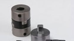
Choosing a coupling with sufficient misalignment accommodation and minimal reactive forces can address reliability problems. Even if a designer puts a flexible coupling between two components, if it isn't the right type of coupling, reactive forces can be high. Consider jaw couplings, often used between motors and pumps. The main purpose of a jaw coupling isn't accommodation of misalignment; it's torsional damping.
Jaw couplings do accommodate some misalignment, but not much. The critical jaw coupling limitation is this: Even if anticipated misalignment between shafts is within its rated misalignment, a jaw coupling still exerts high reactive forces near that limit. For example, a jaw coupling might be rated for 0.010 inches of misalignment, but forcing its two hubs out of alignment by even 0.008 in. can generate several pounds of reactive force.
An Oldham coupling is better suited to radially misaligned applications, with as much as 0.008 in. of misalignment. Unlike jaw couplings, in which the insert is under compression, the active inner component that carries torque is under shear stress. Oldham couplings don't deliver quite as much torsional damping as a jaw coupling, but some Oldham couplings include a midsection machined from urethane and then coated with a low-friction material to address shock. Another option is to use two couplings in series — an Oldham (with the usual midsection made of Delrin-brand material) for misalignment, and a jaw coupling for torsional damping.
Tougher situations
Even Oldham couplings, with their low reactive forces, are unsuitable if there's a risk that the shafts will have more than 0.5° of angular misalignment. In such cases, Oldham universal couplings are more reliable; they accommodate up to 6° of angular misalignment, and as much radial misalignment as classic Oldhams.
Oldham universal couplings are also worth consideration in place of universal joints in applications involving 6° or less of angular misalignment, because traditional universal joints accommodate almost no radial misalignment — so even the small amount of misalignment caused by thermal expansion can result in large forces on bearings.
Speed and balance
If an application involves high-speed rotation (of 5,000 rpm or more) couplings must be balanced. Many couplings have setscrews on just one hub side, for example, and are not dynamically balanced. If these couplings are used in a high-speed application, the resulting vibration can be catastrophic. It hammers away at bearings in motors, driven devices, and other components such as shaft seals.
Even if couplings are nominally symmetrical, two things make some imbalance likely: Manufacturing tolerances and the necessary clearance between the hub's bore and shaft. True dynamic balancing of couplings is one solution. In addition, setscrew hubs can be nominally balanced — three setscrews 120° apart, for example. Couplings from some manufacturers also include nominally balanced clamping-style hubs.
For more information, visit oepcouplings.com or call (419) 298-2306.
About the Author
Steven Elliott OEP Couplings Oren Elliott Products
Inc. Edgerton
Voice Your Opinion!
To join the conversation, and become an exclusive member of Machine Design, create an account today!

Leaders relevant to this article: