Authored by: Darryl McBride Edited by Kenneth J. Korane Key points: • Hoop-style retaining rings are well suited for use with cylinders and thin-wall tubing. • The shaft or housing, not the ring, usually limits load capacity. Resources: |
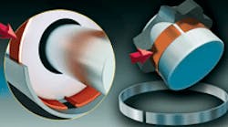
Hoop-style retaining rings offer an innovative way to retain mechanical components when space is limited. Their thin cross section results in minimal radial projection beyond a shaft, and lets them fit into shallower grooves than possible with regular snap rings and retaining rings. Yet the rings handle light to heavy loads and have high thrust capacity. The low-radial profile will not twist or deform under load, as can be the case with conventional retaining rings.
The ring’s thin cross section and precision circularity let it be an unobtrusive component in an assembly, and they are especially suited for applications with thin-wall cylinders. The ring ends flex to simplify assembly and removal without special tools. Internal rings have a bent-end to ease removal. Internal housing rings and external shaft rings are available in standard sizes from 0.375 to 3.0 in. diameters in carbon steel and 302 stainless steel.
Unlike assemblies with Spirolox spiral retaining rings or Circlips snap rings, components held in place by hoop-style retaining rings may have a corner break. Thrust load is not sacrificed when the retained component has a broken corner because the moment arm is negligible.
Groove design
Groove deformation is by far the most common design limitation with hoop-style retaining rings. Unlike a conventional retaining ring or snap ring that fails by deforming and twisting, the hoop retaining rings have superior strength due to a low profile and mechanical advantage under load. There is no moment arm that twists the ring and causes premature failure, as with conventional retaining rings.
However, the shallow groove dimensions of a hoop-style ring makes the groove wall a critical specification. For maximum load capacity, the groove must have sharp corners. The radius on the groove bottom should not exceed 10% of the ring’s radial wall. Maintaining a sharp corner on the top of the groove is just as critical.
Thrust capacity
The shallow groove depth associated with a hoop ring, in combination with the groove material, are the controlling factors in determining thrust capacity. The ring does not twist when loaded, so load-carrying capacity is based on pure thrust load and the yield strength of the groove material.
Calculate allowable thrust load capacity P, lb, based on groove deformation from:
P = DdSyπ/K
where D = shaft or housing diameter, in.; d = groove depth, in.; Sy = yield strength of groove material, psi; and K = safety factor (2 is recommended).
Typical groove material yield strengths are:
• Hardened 8620 steel: 110,000 psi
• Cold-drawn 1018 steel: 70,000 psi
• Hot-rolled 1018 steel: 45,000 psi
• 2017 Aluminum: 40,000 psi
• Cast iron: 10, 000 to 40,000 psi.
About the Author
Kenneth Korane
Ken Korane holds a B.S. Mechanical Engineering from The Ohio State University. In addition to serving as an editor at Machine Design until August 2015, his prior work experience includes product engineer at Parker Hannifin Corp. and mechanical design engineer at Euclid Inc.
