|
Authored by: Edited by Kenneth J. Korane Key points: • Clamped members can be treated as a sleeve or hollow cylinder. Moo-Zung Lee has a BSME from National Taiwan Univ., MSME from Univ. of Houston, and a Ph.D. from New York State Univ. at Stony Brook. He has nearly 40 years experience in power plant construction and dynamic and stress analyses of nuclear-power-plant piping and aerospace and defense systems. |
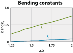
Sound designs of bolted joints rely on a good grasp of their structural behavior, and structural properties of preloaded bolted joints — including the bolt load-sharing ratio, separation load ratio, and joint stiffness — depend only on the stiffnesses of the bolt and clamped members. Nonetheless, bolted joints are rather complicated. Here’s how engineers can approximate bolt and clamped-member stiffnesses and derive structural parameters useful for design.
Bolts and clamped members can be modeled as bars connected in series for stiffness calculations. The stiffness of a bar with uniform cross-sectional area A and length L is related to its modulus of elasticity E = σ/ε, the ratio of stress and strain. If a force F elongates a bar by δ, then the bar stiffness is:
Bolt stiffness
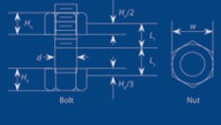
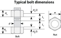
Bolts consist of shank and threaded sections, as shown. Stiffness of the shank is:
where As = πd2/4.
The threaded-section stiffness is:
where At = tensile-stress area of the screw.
The tensile-stress area of the screw can be found in handbooks and textbooks. Or calculate it based on the equation from ASME Standard B1.1-1989 (revision of ANSI B1.1-1982) for unified inch screw threads:
where D = basic major diameter. The basic pitch diameter d2b = D – 0.75 H; H = height of a sharp V-thread or fundamental triangle, H = √3(P/2); and P = thread pitch. 1/P is the number of threads per inch.
Or determine the stress area of the screw based on the area of a circle with the average diameter, da, calculated from the basic pitch diameter, d2b, and minimum minor diameter d1m = D – 1.5 H.
The effective length, Lt, of the threaded section is from the interior end to the midpoint of the nut height. This assumes that bolt tensile force decreases linearly from the seating surface to the free surface of the nut. The effective length of the shank, Ls, includes one-third of the bolt-head height. This assumes bolt force diminishes linearly along the height of the bolt head starting at the mean area of the seating surface. Because the widths across flats of the bolt head are typically w = 1.5d, the mean diameter of stress area in bolt head is dm = (d+w)/2.
Equivalent stiffness of the head in terms of the shank is
For studs with or without threaded inserts, include one-half of the thread-engagement length in the threaded-section length for stiffness calculations. These approximations are judgment calls. Other methods use d/4 in lieu of both Hn/2 and Hh/3. The series spring-connection method may be extended to bolts with multiple diameters.
Calculate total bolt stiffness, kb, from series connection of the section stiffnesses:
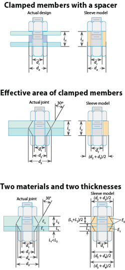
Ac = π(do2– di2)/4
where do and di = outside and inside diameters, respectively. The clamped-member stiffness is:
kc = AcEc/Lc.
Calculate the clamped member stiffness of a solid structural connection using a double-cone load-path model, as shown in the graphic, “Effective area of clamped members.” A 30° cone angle is customarily used in industry. If clamped members have the same modulus of elasticity, the double cone shown is equivalent to the sleeve model.
The double-cone model can be modified to accommodate clamped members with different moduli of elasticity and thickness as shown in “Two materials and two thicknesses.” The stiffness of clamped members is calculated from series connections of three hollow cylinders shown in the sleeve model, assuming L1
Gaskets and seals
Some O-rings rely on internal pressure to entrap rubber in the groove for sealing. These seals may not be in the structural load path and can be ignored for stiffness calculations. In other cases an O-ring may dominate the compliance (inverse of stiffness) of clamped members. For O-rings with solid, hollow, or other cross sections, stiffness data should be translated to the clamped member stiffness for each bolt. For example, if it takes linear force f (force/length) to deform the seal by δ, and the joint has N bolts equally spaced on the bolt center circle with diameter Dc, then each bolt’s share of the spring rate of the seal is: ks = πDcf/Nδ.
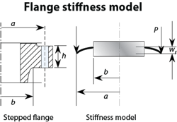
and deflection:
Stiffness of the entire flange as a plate is:
The combined clamped member compliance is the sum of compliance of two flanges and one gasket:
Stiffness of clamped members for one of the N bolts on the flanges is kc = Kc/N.
About the Author
Kenneth Korane
Ken Korane holds a B.S. Mechanical Engineering from The Ohio State University. In addition to serving as an editor at Machine Design until August 2015, his prior work experience includes product engineer at Parker Hannifin Corp. and mechanical design engineer at Euclid Inc.
Voice Your Opinion!
To join the conversation, and become an exclusive member of Machine Design, create an account today!

Leaders relevant to this article: