V-belt selection it's a veritable cinch
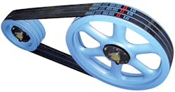
The most common systems for transmitting power from a drive to a driven shaft are belt, gear, and chain drives. But V-belt drive systems, also called friction drives (because power is transmitted as a result of the belt's adherence to the pulley) are an economical option for industrial, automotive, commercial, agricultural, and home appliance applications. V-belt drives are also easy to install, require no lubrication, and dampen shock load.
Here's the catch: Standard friction drives can both slip and creep, resulting in inexact velocity ratios or degraded timing precision between input and output shafts. For this reason, it is important to select a belt appropriate for the application at hand.
Belt makeup
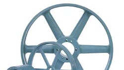
Belt drives are one of the earliest power transmission systems and were widely used during the Industrial Revolution. Then, flat belts conveyed power over large distances and were made from leather. Later, demands for more powerful machinery, and the growth of large markets such as the automobile industry spurred new belt designs. V-belts, with a trapezoidal or V shape, made of rubber, neoprene, and urethane synthetic materials, replaced flat belts. Now, the increased overall surface material of modern belts adheres to pulley grooves through friction force, to reduce the tension required to transmit torque. The top part of the belt, called the tension or insulation section, contains fiber cords for increased strength as it carries the load of traction force. It helps hold tension members in place and acts as a binder for greater adhesion between cords and other sections. In this manner, heat build-up is reduced, extending belt life. Prestretched tension-member cords (polyester, aramide, steel, fiberglass) also minimize stretch.
This file type includes high resolution graphics and schematics when applicable.
The bottom, or compression section, is designed to withstand compression. It is made from a tough rubber compound that exerts a wedging force against the pulley groove to increase adherence without deformation.
The protective cover (generally an elastic cover made of rubber-impregnated fabric that is slip-resistant and durable) is a heat-resistant layer that protects the belt's inner components.
The torque obtained depends on the belt's resistance to the applied tension and the degree of adherence to the inner walls of the pulley groove. For this reason, belt-drive systems should never be lubricated, as they depend on friction to transmit power — in contrast to chain or gear systems that function through pure contact pressure. Another tip: The inside face of the belt should never touch the bottom of the groove.
Horsepower
All belt sizes are classified by cross-section and length dimensions. The cross-section indicates the top width, depth, and V angle dimensions. Length is measured in terms of outside and inside (pitch) lengths.
In mechanical engineering, power is a measure of performance or capacity and is defined as the amount of work performed in a given time. Torque is related to power:
Adding a service factor to nominal horsepower (which is either motor power or horsepower to be transmitted) ensures drive efficiency.
Adjusted power rating
Basic power ratings are known for all belt sheave sizes and drive speeds. With the system presented here, a length correction and an arc correction factor adjust this basic power rating to the sheave speed ratio (which we’ll explain shortly) and the center distance. This is more accurate and realistic than formulas and tables that only show basic horsepower values.
For simplicity, a typical center distance is usually assumed for each sheave combination. For distances not listed, know that longer center distances mean slightly higher power ratings — and shorter center distances mean lower power ratings. For high ratio drives, small centerdistance changes may affect the power rating considerably.
Finally: Many standard sheaves are designed to operate up to 6,500 fpm as per industry standards. Drives exceeding this speed require a ductile iron sheave construction, and in such cases, extra manufacturer design help is highly recommended.
Design horsepower
A service factor takes into account power losses due to vibration, shock, heat, and other factors caused by the motor and application. Using a design power based on these considerations results in a more accurate, efficient drive system.
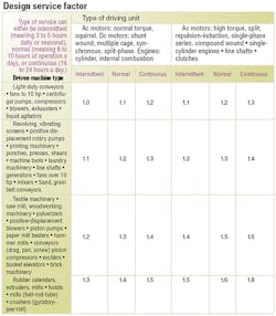
Service factors depend on the driven machines and driving units; select a driven machine with load characteristics closest to those of the machine being considered, then multiply it by the rated motor power or power demand of the driven unit to obtain design power. A service factor of 2.0 is recommended for equipment subject to choking.
HP' = SF × HP
Where SF = Service factor
HP = Basic horsepower
HP' = Design horsepower
Next factor: A ratio expresses the speed relation between two V-belt pulleys. Theoretical speed ratios are stable, because slippage is ignored — about 5% speed loss. However, because belt slip is inevitable, actual ratios vary. If the speed ratio is less than 1 (1:4, for example) it's a system that increases speed; if the ratio is more than 1 (4:1, for example) it's a speed reduction system. In both cases, the ratio is obtained with dimensions of the input (driver) and output (driven) pulley dimensions:
Where RS = Speed ratio
D1 = Driver pulley diameter
D2 = Driven pulley diameter
Rim or belt speed is:
To obtain the maximum recommended operating rpm for a standard sheave or pulley, introduce the 6,500 fpm speed limit with this formula. This speed limit refers only to pulley construction. If the sheave is to be operated at a higher speed, then two-plane or dynamic balancing should be considered.
Balancing
When a unit runs in a circular path, inertial centrifugal force pulls the element away from center. (For a better feel of centrifugal force, tie one end of a rope to an object and the other end to a rotating axis. As speed increases, the object is lifted in the air until the rope extends horizontally.)
In power transmission systems, if the mass of a rotating body is unevenly distributed around its rotational axis, centrifugal forces will be unbalanced. This causes vibration, noise, and reduced life. Sheave balancing on V-belt drives fixes this by altering the center of gravity to correspond with the axis of rotation (at the center of the part).
Every rotating component is unbalanced to some degree; parts with absolute balance would be costly (if not impossible) to manufacture. But two types of balancing approved by the Mechanical Power Transmission Association (MPTA) correct the situation: single and double-plane.
Single-plane balancing is always recommended. Here, a counter weight is added, identical and directly opposite the extra mass. However, single-plane balancing is not always sufficient. If the rpm of the application exceeds the maximum recommended, two-plane balancing is required. Specifically:
Where D = Diameter, in.
F = Face width, in.
For example, if a Ø20 × 10-in. face width sheave runs faster than 1,100 rpm, dynamic balancing is recommended. The result: 1,096 rpm.
When single-plane balancing is insufficient, two-plane balancing corrects weight on two planes on the component axis. (This is not fully dynamic balancing, but partially dynamic balancing.) The areas affected must be separated to effectively produce a two-plane balance as per MPTA guidelines. So, two-plane balancing acts on nonbalanced units of masses that do not lie within a narrow plane. They are distributed along the component length.
Several factors affect total imbalance: The mass of the imbalance source, the distance from rotational center, speed, and the distance between the imbalance cause along the axial length. In general, the longer a component in relation to its diameter, the greater the need for two-plane balancing at a certain speed.
Two-plane balancing is recommended only where the product face width is relatively large and the operational speed relatively fast, or where balance is critical. It is considered optional and must be specifically requested.
Only partial example charts are presented here, but a full technical e-handbook (and software to size belt drives) are available at maskapulleys.com — or call (800) 463-8928.
A newer system for sizing belt drives
When building a new engineering drive or redesigning equipment, there are several approaches to determining the most suitable belt. In one approach, which we present here, adjusted power ratings are used instead of basic ratings. How is this helpful? Basic power ratings are based only on the size of the sheave and drive speed. In the values of the system we present here, length correction and arc correction factors are applied — to adjust the basic power rating to the ratio and center distance. In selection tables here, the adjusted power rating is presented with both correction factors.
Which components are required for a cost-efficient and precise V-belt drive application? To evaluate a selection quickly, follow these steps.
-
Determine drive requirements. How much power do you need to transmit and at what speed?
-
Based on manufacturer ratings, determine the service factor for your particular application.
-
Determine the design horsepower using the formula for it.
-
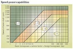
Based on your results, determine which belt section would be appropriate for your drive with speed-power charts. (Narrow belt sheaves, more compact than classic sheaves, have different ratings.)
-
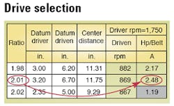
Determine the ratio of your drive application based on the ratio formula and find the closest value in the drive selection tables for your selected belt section. A center distance is preselected based on the drive size.
-
Find the number of belts required by dividing the design horsepower by the horsepower/belt value in drive selection tables.
-
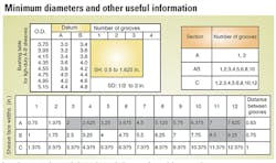
Verify the validity of this drive by consulting the number of grooves available in these sheave sizes.
-
Determine whether dynamic balancing is needed for each sheave based on the dynamic or two-plane balancing formula. Note that standard face width dimensions can be found in tables.
Several associations provide belt specification guidelines. Those established by the Rubber Manufacturers Association (RMA) are most commonly used. Too, drive selection program software makes this process easier.
About the Author
Voice Your Opinion!
To join the conversation, and become an exclusive member of Machine Design, create an account today!

Leaders relevant to this article: