How to Drive Resistive Tactile Sensors
Authored by: Edited by Leland Teschler Key points: Resources: Wikipedia page on tactile sensors in robotics, en.wikipedia.org/wiki/Humanoid_robot |
Thin-film force sensors are generically referred to as tactile sensors. The term comes from their frequent use as a means of sensing a nuanced or delicate touch as with a robotic hand from a humanoid robot. But tactile sensors have applications extending far beyond anthropomorphic robots. They typically are built on flexible circuit material so they can be thin, light, and flexible. This opens up such potential applications as, for example, sitting under a bolt head to sense the load as a technician wrenches the nut tighter, or to measure the contact pressure distribution between two print rollers from within the nip.
The first generation of thin-film force sensors emerged in the 1980s. Developed for the dental industry, they let clinicians measure the force of a patient’s bite with respect to time. Since the 1980s, the technology has been further refined and applications have emerged in such areas as conformal ergonomics, large metalstamping machines, small electronic connections, and even soft-rubber door seals.
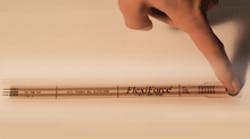
One such tactile sensor is called a FlexiForce sensor. It consists of special, proprietary piezoresistive material sandwiched between two pieces of flexible polyester with printed-silver conductors on each inner half. The conductive traces form electrical connections to external circuits. The resulting sensor is paper thin, only about 8-mil thick.
How to drive a flexible force sensor It is possible to adjust the drive voltage of the recommended drive circuitry to alter the way the sensor responds to force, so the curve can actually be shifted left (higher drive voltage) or right (lower drive voltage). This either increases or decreases the dynamic range (and accuracy since repeatability and hysteresis are both based on full-scale force range). Also, adjusting the feedback resistor (higher to reduce the full-scale range or lower to boost the full-scale range) further changes the output, but this doesn’t change the curve. It just controls where the sensor “saturates” on the curve (typically 10 to 20 kΩ). |
FlexiForce sensors are basically resistors that vary linearly in conductance versus force under an applied load. With no force applied, their resistance is on the order of megaohms — essentially an open circuit. As applied force rises, output resistance drops, eventually diminishing to about 10 k or lower, depending on the application. The output, expressed in conductance versus force, is quite linear (linearity error < ±3%). External circuitry to convert the output into a linear analog voltage can be relatively simple.
The range of force these sensors handle can be customized and they can be quite sensitive to applied force. A FlexiForce sensor can register a light touch of only 5 gm, though recommendations are to load at least 80% of the device’s sensing area with 40 gm or more for best results. It is also possible to adjust the sensor’s dynamic range by tweaking its external drive circuit. These adjustments are as easy as a turn on a potentiometer.
FlexiForce sensors are driven with dc. They have a response time of 5 to 15 μsec at most, and a frequency response of about 2 kHz. The standard version of the sensor has an active sensing diameter of 0.375 in. In many cases, designers will prototype with a standard sensor to prove a concept, then devise a custom version. Custom sensors can have nearly any shape and can be comprised of single or multiple sensing points. Sensors can also be attached to stiffer substrates such as hard plastic or metal if the application environment demands it.
Standard sensors handle forces in the range of 0 to 1, 0 to 25, and 0 to 100 lb. Overloads up to 10,000 psi (plastic limit) won’t harm the sensors. However, it is possible to adjust the drive voltage to the sensor as a means of managing its sensing range. This is useful because there is a radical change in sensor resistance at relatively low applied force as the resistance changes from an open circuit to hundreds of kiloohms. This change is somewhat unpredictable. Boosting the drive voltage shifts the operating point to the left on the sensor resistance curve and away from the area of drastic resistance change.
Similarly, it may be desirable to keep the sensor from operating in the area where large changes in applied force produce relatively little change in resistance. Limiting the drive voltage keeps the sensor out of this part of its range.
Manipulation of sensor-drive voltage effectively shifts the curve to the left or right, making the sensor more or less sensitive to applied force. It is common practice to adjust drive electronics so sensors remain in the range of 10k to 20 kΩ during normal operation. Nevertheless, there are trade-offs associated with manipulating drive voltage this way. For one thing, operating the sensor over just a subsection of its range effectively reduces its accuracy, repeatability, and hysteresis because these parameters are all based on the sensor’s full-scale force range.
In addition, there is a limit to the amount of drive voltage adjustment that is reasonable. A safe upper limit is about 10 V. Driving these sensors below about 1 V brings resolution issues. A rule of thumb is that it should be possible to manage applications with up to a maximum of 10× change in drive voltage. When this is not the case, it’s time to switch to a sensor having the next highest or lowest force range for best results.
