The difference between ac electrical power and ac electrical energy
It's essential to understand how power and energy calculations relate, especially with the increased importance of energy efficiency.
Calculations of power and energy are relatively straightforward when the subject is strictly dc circuits.
The situation is more complex in the ac world, however.
Here's how calculations of electrical power and energy relate to each other ... the basics of watts and watt-hours.
In a dc circuit, the power, P, developed in any component of the circuit is:
P = V × I
where P is in watts, W
V is the potential difference in volts across the component, V and
I is the current through the component in amperes, A.
Power is the rate of doing work or, equivalently, the rate at which the circuit transmits electrical energy. Energy can exist whether or not there is any work done. The amount of energy converted into work, or consumed, is equal the product of power and time.
Consider the dc case where power is steady over time. Then the energy consumed J is:
J = P × t
where P in watts, t is in seconds, and J is in joules or watt-seconds. The more typical unit of energy for ac power circuits is watt-hours, Wh. In this case, t is in hours. If P is in kilowatts, kW, and t is in hours, J has units of kilowatt-hours, kWh.
In most real-world circuits, power consumption is not steady. In this case, the power must be integrated over the specified period of time to determine the energy consumed:
J = ∫T2Pdtwhere the period between T1 and T2 is the interval of interest.
In addition, integration takes place by summing up the power consumed over specific intervals.
Case in point: electromechanical power meters
Consider electromechanical power meters normally found in residential housing, which use a metal disc that rotates at a speed proportional to the power passing through the meter. The number of disc revolutions is proportional to the energy use. The disc is acted upon by two sets of coils.
• One coil produces a magnetic flux in proportion to the line voltage.
• The other produces a magnetic flux in proportion to the current.
The magnetic fields of the two coils are oriented in such a way as to produce a force on the disc that is proportional to the product of the instantaneous current, voltage and phase angle (power factor) between them. A permanent magnet exerts an opposing force proportional to the speed of disc rotation. The equilibrium between these two opposing forces makes the disc rotate at a speed proportional to the rate of energy use. A register mechanism counts the revolutions to register the total energy used.
Of course, in dc circuits, power is just equal to the current multiplied by the voltage. The situation in ac circuits is more complicated because current typically lags the voltage. This relationship enters into power calculations and also can lead to some misunderstandings about differences between power and energy.
To calculate ac power, the usual approach starts with the equations for instantaneous voltage and current:
i = Im sin ωt
e = Em sin (ωt + θ)
where Im and Em are the maximum current and voltage respectively, θ is the angle of lag of the current behind the voltage, and ω is 2πf — where f is the ac freqency.
Multiplying these two relationships together yields the ac power.
With some mathematical manipulation of e and i, it can be shown that the average ac power — EI — is:
E I = Em Im / 2After some further mathematical manipulations, the average ac power P is:
P = E I cos θ
Here cos θ is actually the power factor. Solving the above equation for cos θ yields:
| P |
| EI |
=
| True power |
| volt-amperes |
The quantity E I — volt-amperes— is sometimes called apparent power. The name comes from the fact that E I is simply what's obtained from reading a voltmeter and ammeter and multiplying the two readings together.
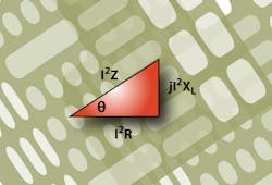
To show power relationships in ac circuits, it is often convenient to start with the well-known phasor diagram representation of an ac circuit:
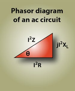
θ is the angle of lag of the current behind the voltage, as before. To obtain what's called the power triangle shown here, each side of the triangle is multiplied by the average current I.
I × (I Z) = I2 Z = E I
I × ( I R) = I2 R = E I cos θ
I × (I XL) = I2 XL = E I sin θ
Here sin θ is called the reactive factor.
The term E I sin θ is called reactive volt-amperes and is given in units of var.
One source of confusion associated with reactive volt-amps is that they are sometimes referred to as a measure of reactive power. In reality, reactive volt-amps are a measure of energy, not power. Reactive volt-amps represent the energy supplied to the circuit during part of the cycle, then returned to the system during the part of the cycle when the system inductance is discharging.
About the Author
Leland Teschler
Lee Teschler served as Editor-in-Chief of Machine Design until 2014. He holds a B.S. Engineering from the University of Michigan; a B.S. Electrical Engineering from the University of Michigan; and an MBA from Cleveland State University. Prior to joining Penton, Lee worked as a Communications design engineer for the U.S. Government.
Voice Your Opinion!
To join the conversation, and become an exclusive member of Machine Design, create an account today!

Leaders relevant to this article: