Team Collaboration Across CAD/CAM Workflows
What You’ll Learn:
- Strategies for CAD/CAM workflow.
- Managing data across applications.
- Challenges of future methods in manufacturing.
Since the First Industrial Revolution at the end of the 18th Century, mechanical innovations have enabled efficient ways to create products and consumer goods to meet society’s demands.
Over the years, manufacturing methods have evolved, adapting new technologies and created new processes. For example, the use of electricity marks the beginning of the Second Industrial Revolution, introducing mass production and the development of the assembly line.
Subsequent research, beginning in the 1950s, enabled the integration of computers and the initial automation of processes by the mid-1970s, marking the onset of the Third Industrial Revolution. At this stage we can mark the first interactions between CAD (computer aid drafting) and CAM (computer aid manufacturing).
We can define CAD/CAM as the interaction and dynamic interchange of data in a unified computer-based environment, aimed at manufacturing purposes. This interaction allows us to transfer modeled data to computer control machines that can transform these models into physical products.
CAD/CAM Workflow and Manufacturing Teamwork
Some advantages of the integration of CAD/CAM are:
- Improved precision and quality
- Reduced processing times
- Increased productivity and lower costs
This integration also fosters collaboration by bringing together cross-disciplines—such as designers and programmers—who work and communicate effectively toward a common goal.
READ MORE: Design Engineer Demonstrates Extrusion Crosshead Prototype with Camlock Head
However, customizing a common work environment can be challenging. Multiple variables need to be defined, such as file sharing across applications and machine operations that are both compatible and accessible.
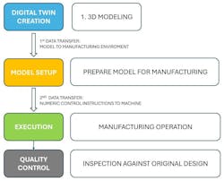
CAD/CAM workflow steps (see Fig. 3 above)
- Digital twin creation. Modeling of design based on specific function-performance requirements.
- Model setup. Preparation of the model for manufacturing. It includes the first transfer of data to a digital manufacturing environment, defining machine operations, toolpaths and simulations.
- Second data transfer. Post-processing, file-sharing mechanism to allow the machine to understand the instructions of the manufacturing setup.
- Execution. CNC machine executes the manufacturing operations to transform the digital design into a physical object following the instructions provided.
- Quality control. Physical object (part) is inspected to verify accuracy and match the original model/design.
Integration of the Design and Manufacturing Operations
Markkus Rovito defines “Design for Manufacturing” as follows: “Design for manufacturing (DFM), or design for manufacturing and assembly (DfMA), is a design methodology that enables and optimizes prefabrication through a set of design choices and principles. Products and components are designed specifically for manufacturing and to make manufacturing processes easier and more cost effective. It involves designing and producing with specialized CAD and CAM software.”1, 2
The definition defines the design for manufacturing concepts. This consists of orientating a design intent to follow strategies such as modular design, reduction of part count and standardization of connections. This strategy will define the design outcome, its future optimization and adaptability.
Additionally, it establishes the necessity of specialized CAD/CAM Software to enable common activities.
We can summarize the requirements to enable common activities or dynamic collaboration as follows:
- Capacity to store and export data for common work.
- Capacity to share and manipulate data across applications (key factor of workflow dynamics).
- Capacity to establish a transparent mechanism to communicate software to hardware.
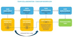
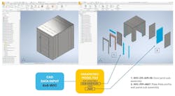
Figure 4 above represents an example of an ideal scenario for data sharing and team collaboration.
When a design is created with specific parameters and the data is shared or transferred while maintaining a parametric link, programmers can receive real-time updates for any changes made to the original model.
Nowadays, existing software such as Fusion360 offers full packages of CAD/CAM/CAE integration, with different environments, where the same file can be manipulated across applications.
Other software, such as Solidworks or Inventor, support the addition of integrated CAD applications like SolidCAM or InventorCAM. These applications can be purchased and added to the software tool palette to expand machining tool capabilities within the CAD environment.
READ MORE: Ensuring Parts Fit, Using Bonus Tolerance to Your Advantage
There are also fully integrated CAM software applications, such as Mastercam and Esprit, where CAD models can be exported for manufacturing setup.
In this context, everything would depend on each industry’s capacity and financial resources to acquire specific software packages, while also considering the importance of managing shareable data and compatibility.
Review of CAM Operations
For this section, we will review a case study as an example of CAD/CAM dynamic collaboration.
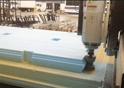
- Case study. (See fig. 5 above)
- Design. Walk-in cooler: model 6 ft × 8 ft with remote A/C compressor unit
- Parts to review. Standard 47 in. × 86 in. wall panel and standard door jamb
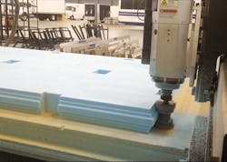
- Material. Styrofoam stock: 4 ft × 8 ft × 4 in
- Software. Autodesk Inventor – Fusion360
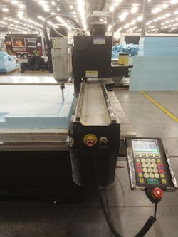
- Machines. 3 Axis CNC Router, AXYZ Infinitive 4010 ATC / Multicam 3000 Series
- Operations. 3 axis mill operations
First Data Transfer: (See fig. 6 above)
In this case study, we transferred Inventor .IPT files to Fusion360, as both software packages are from Autodesk. The data is compatible across formats because they share a common underlying file structure.
For different scenarios, alternative options need to be implemented to maintain data compatibility. A commonly used example is STEP files, or Standard for the Exchange of Product Data Files.
STEP files are ISO standard cross-platform, compatible with many CAD software.
These files are built using NURBS (Non-Uniform Rational B-Splines), which are mathematical models of 2D/3D data.
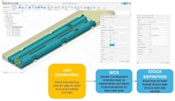
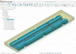
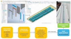
CAM Setup and Programming (see fig. 7 above)
Initially, we took an existing primitive program, keeping original tooling configurations.
Secondly, the toolpath configurations were optimized to reduce waste, enable nesting and common cutting of parts and improve finishing of profiles.
The development of the project involved two stages. First, Inventor and InventorCAM were used to coordinate design and manufacturing.
Subsequently, due to changes by the client/company, all CAM setups were migrated to Fusion360, also running a new CNC router but keeping the original Inventor design files.
Second Data Transfer
Post Processor: A post processor is software that translates instructions from CAM into numeric control codes.
Each machine requires a dedicated post due to the differences in machine parameters and kinematic capabilities.
The script configuration of the post will provide information on travel axles, feeds and speeds and tool usage.
Tooling and Operations
Operations need to be set one step at a time, in a logical and sequential order. This means, each operation should prepare the part for the next one.
A straightforward example is roughing operations on turning or multi-axis milling, where the bulk stock of the part is removed in a series of overlapping passes.
This operation gets close to the final contour of the part, allowing the surface to be subsequently refined by a finishing operation.
To manufacture the WIC (walk-in cooler) parts, 2D contour and pocket operations were mostly implemented to create the variation of geometries required to interconnect the parts.
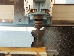
As for tooling, four tools were used: two form mills (male and female profile), one straight cutter and a 60 deg. chamfer.
Following is an overview of two of these tools:
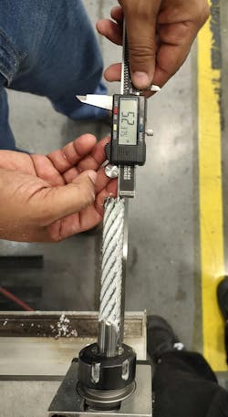
A straight cutter is used in 2D contour operation, following the model outliner to define a true edge around the part. (See figs. 8 and 9 below)
Additionally, it is used for pocket operations on more complex parts such as door jamb header/legs or corners.
A form mill is used in 2D contour, defining the final male profile. (see figs. 10 and 11 below).
Future Trends
We have presented a basic but efficient example of the dynamics of teamwork coordination, exploring the challenges of managing data across applications.
Communication among colleagues with diverse skills and technical backgrounds fosters positive technical feedback throughout the various stages of the manufacturing process. The ongoing exchange enables continuous improvement and leads to optimal results.
READ MORE: Closing the Manufacturing Loop (Part 3): CAD/CAM, Design for Manufacturing and Simulation
At the peak of production, the client/company achieves a total of 50 units of walk-in coolers and walk-in freezers per month, offering different configurations and sizes. DFM strategies developed with the client or company’s manufacturing capacity in mind made this possible.
Finally, we need to take into consideration the state of the art and future developments of manufacturing processes to understand the future role of CAD/CAM workflows as well. The term “Industry 4.0” was coined in 2011 to mark the beginning of the Fourth Industrial Revolution. This technological stage is in current development and evolution and connects the capabilities of robotics, AI, cloud servers, Internet of Things (IOT) and accelerated manufacturing methods such as 3D printing.
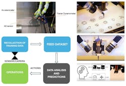
These new methods and setups interconnect highly efficient digital/physical systems that are capable of accelerating processes. Furthermore, machine learning fed by sensors can collect live data during operations, creating datasets that can be analyzed to recognize patterns and use this info to autocorrect and predict possible failures (see fig. 12 below).
In this context, what will the future role of designers/programmers be, especially as human interaction appears to be increasingly minimized?
To remain relevant, designers and programmers will need to develop a range of new skills. Basic coding skills and a foundational knowledge of large language models are essential to understanding AI and machine learning processes and interactions. Manufacturing dynamics are changing for sure—and they continue to do so—as part of ongoing technical progress.
Keeping up with the rapid pace of new advancements can feel overwhelming at times.
Nevertheless, it is important to view these changes as positive challenges. By continually updating and upskilling, we can prepare for the opportunities ahead.
References
- Quote from: Rovito, Markkus. (2022). “Smart Manufacturing: The Future of Making is Digital.” Design and make with Autodesk. https://www.autodesk.com/design-make/articles/smart-manufacturing
- Kao, Yung-Chou. (1997). Development of International Collaborative CAD/CAM. Research Gate. MMS Collections: CAD/CAM. Modern Machine Shop. Mmsonline.com
About the Author

LR Brines
LR Brines is an architect, industrial designer and CNC programmer. He specializes in the implementation of digital fabrication methods for construction applications. Brines provides consulting services for several construction and manufacturing companies in the Central and South Florida area.
Voice Your Opinion!
To join the conversation, and become an exclusive member of Machine Design, create an account today!

Leaders relevant to this article: