Drawing Inputs Engineers Should Define Before Specifying a Custom Polymer Sleeve Bushing
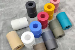
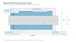
A sleeve bushing is often represented by three dimensions: inside diameter, outside diameter and length. That geometry may be enough to create a CAD feature, but it is rarely enough to define a functional polymer bearing. A supplier still has to determine what the bore mates with, how the outside diameter is retained, which loads act on the part, what the environment does to the material and which characteristics must be verified. If those inputs are absent, the quotation may be based on assumptions that do not match the design.
The problem becomes more important with polymers because dimensions and running clearance can respond to temperature, moisture, chemical exposure, installation strain, creep and the material’s processing history. A tighter tolerance is therefore not automatically a better tolerance. It may add inspection cost while failing to control the condition that matters in service. The following seven input groups give design engineers a practical way to prepare a sleeve-bushing drawing for manufacturability review.
1. Define Complete Geometry and the Datum Scheme
Start with the nominal bore, outside diameter and axial length, but also show every feature that changes how the bushing is made or installed. These may include a flange, split, slot, lubrication groove, lead-in chamfer, radius, shoulder or anti-rotation feature. State the units and identify which end or surface establishes the axial reference. If the part is controlled by a 3D model, define whether the model or the drawing governs when the two disagree.
The drawing should distinguish functional features from reference dimensions. For example, bore size may be critical to running clearance, while an outside corner break may only be needed to protect the housing during assembly. A datum scheme should reflect how the bushing is located in the assembly and how it can be inspected. Concentricity-like requirements should not be added by habit; use a geometrical control that expresses the actual functional relationship and can be measured with the available method. ASME Y14.5-2018 (R2024), or the applicable company drawing standard, can provide a common interpretation framework.
2. Define Fit, Mating Parts and Assembly Sequence
A polymer bushing does not function by itself. Provide the shaft diameter and tolerance, the housing bore and tolerance, and the required condition after installation. State whether the outside diameter is intended to slip into the housing, be lightly retained or be installed with interference. Also state whether the final inside diameter is specified before or after press-in. An interference fit can reduce the installed bore and the amount depends on geometry, material response and housing restraint.
The assembly method belongs in the specification package. Press direction, available lead-in, adhesive use, mechanical retention and replacement method can all change the feature design. A split sleeve may simplify installation but changes how the bore closes. A flange may react to axial load, serve as a stop or merely locate the part during assembly; the drawing should identify which function applies.
If a standard limits-and-fits system is used, cite the exact system and revision. ISO 286-1:2010, for example, defines a code system and terminology for linear-size tolerances and fits, but a fit designation alone does not capture polymer installation effects or service-temperature clearance. Record the functional minimum and maximum clearance at the relevant condition rather than relying only on a familiar fit label.
3. Describe Load and Motion as a Duty Cycle
Specify whether the bushing sees radial, axial or combined load and whether the load is steady, reversing, impacting or edge-concentrated. For radial loading, provide enough information to calculate projected bearing pressure from load divided by projected area. For motion, distinguish continuous rotation, oscillation and linear sliding. Include shaft speed or surface velocity, oscillation angle and frequency, stroke length, starts and stops, and the proportion of time the system operates.
Pressure-velocity screening can be useful, but a single PV number is not a complete design rule. Counterface finish, alignment, heat rejection, lubrication, contamination, edge loading and duty cycle influence wear and temperature. State the required life in cycles, hours or travel distance and define the allowable end condition, such as wear depth, clearance growth, torque or positional error. This converts “long life” into a reviewable criterion.
4. State Temperature, Media and Surrounding Conditions
Provide continuous, peak and cycling temperatures, where temperature is measured and how long each condition lasts. Ambient temperature may differ from the contact temperature generated by friction. If the bushing is installed in a metal housing, consider that the shaft, housing and polymer may expand at different rates. The clearance calculation should cover the assembly and operating states that matter, not only room-temperature inspection.
Identify every fluid, gas, cleaner or process chemical that contacts the part, including concentration, exposure time and whether exposure is continuous or intermittent. Also state lubrication condition, pressure or vacuum, abrasive particles, radiation, outdoor exposure, electrical needs and cleanliness constraints when applicable. Do not replace this information with a broad phrase such as “chemical resistant.” Compatibility is a property of a specific material and exposure condition and the complete assembly may introduce additional limits.
5. Specify Material by Grade and Required Evidence
Generic labels such as PTFE, nylon, PEEK or UHMW-PE describe material families, not complete purchasing specifications. State the exact grade when it is already qualified. If grade selection is part of the supplier’s review, identify the properties that must be prioritized—for example, deformation resistance, wear behavior, electrical characteristics, low friction or compatibility with a named medium.
Filled polymers require particular care. Filler identity and proportion can change mechanical, tribological, electrical and dimensional behavior, so formulations should not be treated as interchangeable. Also separate material history from compliance. Terms such as “virgin” or “reprocessed” do not by themselves prove food-contact, medical, electrical or other regulatory suitability. If a project requires a declaration, certificate, test report or lot traceability, name the exact document and the entity or item it must cover.
6. Include Prototype and Production Quantities
Quantity affects the feasible manufacturing route, tooling decision, inspection plan and unit economics. State the immediate sample or first-article quantity, expected production lot size and annual demand. Also note whether the design is frozen or likely to change after testing. A supplier can then distinguish a development batch from a recurring production requirement instead of assuming that a one-piece request represents the final volume.
Ask for manufacturing feedback before forcing a process onto the drawing unless the process itself is a design requirement. A prototype may be machined from available stock while a stable production design could justify a different near-net route. The important engineering question is whether the selected route can maintain the functional features and evidence requirements at the stated quantity.
7. Define Inspection, Records and Acceptance
Mark critical characteristics and state how acceptance will be determined. Include the inspection condition, measurement method or gauge concept when it affects the result, sampling level, rounding rule and any required first-article approval. ISO 1:2022 defines a standard reference-temperature concept for dimensional specification and verification; the drawing or quality plan should state any temperature-conditioning requirement relevant to a polymer part.
Avoid applying the tightest tolerance to every dimension. Prioritize the installed bore, housing interface, axial location, wall relationship or other features that actually control function. Surface texture should be assigned only where it supports assembly, motion, sealing or wear. If visual limits, cleanliness, packaging, labeling, material records or certificates are required, define them before quotation rather than after the first batch is made.
A complete request normally includes a controlled PDF drawing, a STEP or DXF file when useful, the shaft and housing interface dimensions, the seven input groups above, sample and production quantities and the required records. For a replacement bushing, add the current part, observed failure mode and any available wear or clearance measurements. These details help separate a material problem from misalignment, edge loading, thermal closure, contamination or an assembly condition.
The goal is not to place every possible note on one drawing. It is to make design intent explicit enough that engineering, sourcing, manufacturing and inspection teams evaluate the same operating condition. When geometry, interfaces, duty, environment, grade, quantity and acceptance evidence are defined together, a simple sleeve becomes a specification that can be reviewed without hidden assumptions.
About the Author
Chuanping Lu
Sales Department Manager, Pengrowth Technology Co., Ltd.
Voice Your Opinion!
To join the conversation, and become an exclusive member of Machine Design, create an account today!
 Leaders Logo
Leaders relevant to this article: