Calculating the Hidden Loads in Fasteners Near Edges
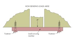
Fasteners installed near the end or edges of load-carrying members often carry more than just the applied load. They also carry a hidden load generated by bending moments in the load-carrying member. This additional load may outweigh the applied load by a great deal.
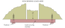
If the load–carrying member in the image below were infinitely rigid, the fastener would be required to resist only the applied 2P. But in most applications, a different loading condition develops. The flexibility of the load-carrying member typically demands that is edges or ends resist angular rotation caused by local loads.
For this analysis, bearing loads are assumed to be at a maximum at the edges, tapering to zero at the fastener centerline with a triangular load distribution. Under these conditions, fastener loads and stress are from:
σmax = 24sm/(8ws3 – 4R3)
P1 = σmax/6s(3ws2 – 4R3)
To use these equations, M, the resistive moment created by the bearing load, is conservatively set equal to the bending moment needs to maintain a fixed-end constraint of the load-carrying member. Then the first equation determines the maximum bearing stress and the second equation determines the resultant bearing load on the fastener.
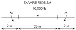
Example: A 5-in wide bar is centrally loaded by a force of 10,000 lb and restrained at each end by a fastener passing through a hole with a radius of 0.5 in. The distance between the holes’ centerline is 36 in and the distance between the fastener centerline and the bar end is 2 in. What are the maximum bearing stress and maximum load on the fasteners?
From elementary strength of materials,
M = 2PL/8 = 10,000(36)/8 = 45,000 in-lb
Then maximum stress is found from the first equation as:
σmax = 24(2)(45,000)/[8(5)(2)3 – 3π(0.5)4
= 6,800 psi
The bearing load, from the second equation, is then:
P1 = 6,800/6(2) [3(5)(2)2 – 4(0.5)3]
= 33,700 lb
The maximum load on the fastener is thus the bearing load plus half the applied load, or 38,700 lb.
Nomenclature:
L is the distance between fastener centerlines, in.
M is the resistive moment provided by the bearing load, in-lb.
P is half of the total load on the load bearing member, lb.
P1 is the resultant bearing load on the fastener, lb.
R is the radius of the fastener holes, in.
s is the distance from the fastener centerline to the end of the load carrying member, in.
w is the width of the load carrying member, in.
σmax is the maximum bearing stress, psi.
Looking for parts? Go to SourceESB.
