Small stepper motors pack a punch despite their limited stature. Such motors are well known for their excellent open-loop positioning characteristics and for delivering relatively high torque, but even higher performance can be achieved with an often overlooked configuration. Fitting a gearhead to a stepping motor can increase torque and resolution, reduce vibration, and let a relatively small motor drive large inertia loads.
When a gearhead is added to a stepping motor, the increase in output torque can be calculated by multiplying the motor torque at the desired speed times the gear ratio times the efficiency of the gearhead.
Tout = Tmotor x i x η
where
Tout = output torque at gearhead shaft
Tmotor= output torque of stepping motor
I = gear ratio
η = gearhead efficiency
All stepping motors have a resonant frequency in the 150 to 300 steps/sec range, which can cause the motor to vibrate or miss steps. Adding a gearhead can reduce this vibration. In order to obtain the same shaft speed, the frequency of the input pulses needs to be increased. After increasing the input frequency, the motor will no longer operate within the resonant frequency range and will run more smoothly.
Inertia basically determines how quickly a load will accelerate or decelerate. In general, it is recommended that the ratio of load inertia (reflected to the motor shaft) to the rotor inertia be 10:1 or less. The more quickly you intend to accelerate or decelerate, the lower the ratio should be. A gearhead reduces load inertia reflected to the motor shaft by the square of the gear ratio. For example, if a load has inertia of 1,600 oz-in.2 and a 7.2:1 gear ratio is used, the inertia reflected to the motor shaft will be 30.9 oz-in.2
Jref = Jload/i2
where
Jref = reflected inertia at the motor shaft
Jload = load inertia
I = gear ratio
The gearhead ratio also has an effect on step resolution. For example, a 7.2:1 gearhead attached to a stepping motor that moves 0.72°/step would have step resolution of 0.1°/step at the gearhead shaft.
Resout = Motorres/i
where
Resout = resolution at gearhead shaft
Motorres = motor resolution
i = gear ratio of gearhead
No free lunch
Of course, you don’t get something for nothing. There are some tradeoffs when a gearhead is used, such as reduced output speed and positioning errors in the mechanical system. The speed of the gearhead shaft is reduced by the ratio of the gearhead.
Ngear = Nmotor/i
where
Ngear = speed at gearhead shaft
Nmotor = motor speed
i = gear ratio
The positioning errors are caused by backlash and angle transmission error. Backlash is often intentional, providing space for machining errors and for lubrication to adhere to the gear teeth. However, when a gearhead is combined with a stepping motor, this space or clearance introduces positioning errors during forward and reverse operation. The amount of backlash depends on the type of gearhead used. Angle transmission error is caused by machining errors on the gearhead teeth and appears as the difference between the actual shaft output angle with respect to the actual motor input angle.
Continue on page 2
Planetary solution
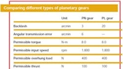
One way to combat backlash in a geared stepper motor is employment of planetary gears. With their compact configuration and high power density, it is possible to increase the size of the final gear stage (internal gear) over that of the parallel axis gear.
In a planetary gearhead, the torque input from the sun gear is distributed and transmitted by three planetary gears and delivered by the carrier (output). Because this configuration involves multiple planetary gears, it provides greater transmission torque than a parallel axis set-up of similar dimensions. What’s more, a planetary gearhead can be arranged such that the output axis coincides with the center axis of the motor.
Planetaries don’t eliminate backlash completely. For this, additional measures are needed to preload the gears. One of the more simple ways of doing this is the scissors method.
Most planetary gear trains are arranged in two stages allowing for three planetary gears. This ensures more effective load distribution, and makes it possible to take full advantage of planetary gears’ greater torque transmission.
When a scissors gear is used in a planetary configuration, each gear train has two planetary gears and two internal (ring) gears per sun gear. In the planetary gear method, the sun gear, planetary gear, and internal gear mesh at three points simultaneously. Backlash is eliminated at two positions – between the sun gear and planetary gear and between the planetary gear and internal ring gear.
Backlash be gone
In order to improve the accuracy of geared step motors, backlash and angle transmission error must be reduced. The angle transmission error can be improved by increasing the part’s machining accuracy. But, more complicated situations call for more sophisticated methods of backlash reduction.
• Scissors gear method
Two gears on the driven side are meshed with one gear on the drive side. When the gears on the driven side are turned after assembly, backlash is present if one gear on the driven side is meshed with one gear on the drive side. However, backlash is not present when two gears on the driven side are meshed with one gear on the drive side.
• Tapered gear method
A tapered gear is placed where the gear profile is shifted. After assembling, the gear is shifted in the axial direction to remove backlash without increasing the number of parts.
• Double row gear method
Two gear trains are provided. After all gears have been assembled in the gearbox, one gear is turned to eliminate backlash. This method eliminates backlash as an output, although backlash is present in a single gear. Furthermore, torque is transmitted through different paths, depending on the direction of rotation. This method ensures that backlash produced by a combination of gears on two or more stages is eliminated at one position.
Nick Johantgen is engineering manager at Oriental Motor USA Corp., Los Angeles.
Related Articles
Silencing high-speed gearheads
Gearheads push performance envelope
About the Author
Voice Your Opinion!
To join the conversation, and become an exclusive member of Machine Design, create an account today!

Leaders relevant to this article: