Taking Connectivity to a Higher Level
Any electronic or electrical control panel is likely to require wiring connections. Whether the application is for a consumer device, commercial equipment or industrial system, designers need to select reliable products that are easy to install and will operate reliably for many years. Terminal blocks meet these requirements and are the most common way to interface electrical field wires with panel-mounted electronic and power systems.
The most common—and traditional—screw-type single-level terminal blocks are a simple solution, but not always the most efficient use of space or labor. Especially when one considers that many wires are installed in functional pairs or triplets, it becomes apparent that multi-level terminal blocks offer design advantages. Also, newer spring-type mechanisms are more reliable and easier to install than screw-type products. When selecting terminal blocks for any application, designers should consider the form factor options and other product characteristics to obtain the best performance.
Terminal Block Basics
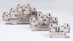
A basic terminal block consists of an insulated housing—usually some form of plastic—which can be mounted onto an industry-standard DIN rail or bolted directly to a back panel within an enclosure. For compact DIN-style terminal blocks, the housing is often open on one side. The blocks are designed to be stacked together for maximum space savings, and an end cover is only required on one end of the stack (Fig. 1).
“Feed through” terminal blocks commonly have a wire connection point on each side and a conductive bar connecting between those two points. Traditional terminal blocks just handle one circuit each, but newer designs can have multiple levels and may also include convenient grounding provisions for cable shields.
Classic wire connection points are screws, sometimes using washers. The wire needs to have a ring- or U-lug crimped on to the end, which is then installed and tightened under the screw. Alternate designs incorporate the terminal block screw connection into a cage clamp, so that bare wires or wires with a simple post-like ferrule crimped on to the end can be installed directly into the cage clamp and secured.
A more recent development is spring-loaded connection points, which do away with the screw entirely. Early designs required use of a tool to push the spring down, which would open the connection point so the wire could be inserted. Not only can spring designs be wired more quickly than standard screw-type components, but the constant spring pressure also resists vibration better than screw-type terminals.
An improvement on this spring cage design is called push-in design (PID), which is arranged so that solid wires or ferrule-crimped wires can be pushed directly into the terminal block without need for a tool. For PID terminal blocks, a simple tool is used to release the wire, or to install bare stranded wires. Spring-type designs can reduce wiring labor by at least 50%.
There are also some common and useful terminal block accessories. Plug-in bridge bars can be inserted quickly to cross-connect multiple terminal blocks at a time, providing a compact method of power distribution. Marking provisions are important to provide clear identification for each terminal block conductor, and partition plates allow designers to provide a noticeable means of segregating one or more terminal blocks from each other. Some terminal blocks incorporate a fuse or disconnect means right inside the block, so additional components are not needed to perform this function.
Keeping Circuits Grouped
For control and automation panels, the power distribution circuits—whether 24 V DC or up to 240 V AC—usually require two wires. Signaling applications, such as connectivity to sensors, are typically 2-wire or 3-wire, and may require an additional shield connection for analog signals.
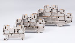
Certainly, it is possible to install all these wire connections across many single-level terminal blocks. However, there are many initial and ongoing benefits to stacking all the connections for a given circuit into one multi-level terminal block (Fig. 2).
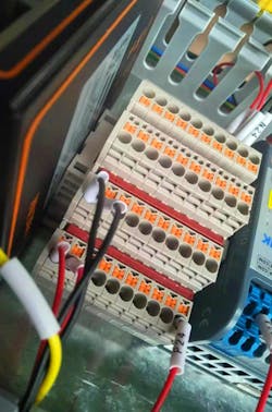
Multiple conductors making up a circuit, especially for analog signals, are often run in one multi-conductor cable instead of as individual conductors. Because they are already grouped within one cable, it simply makes sense to terminate all of these related conductors onto one multi-level terminal block, instead of several single-level terminal blocks. Multi-level terminal blocks speed up installation, and they make it easier for personnel to troubleshoot any issues because all of the conductors are close together (Fig. 3).
One possible downside of multi-level terminal blocks is if they are so small that it is hard to work with the multiple conductors involved. As long as the physical dimensions are balanced and marking provisions are clear, the benefit of higher wiring density takes precedence. For a typical 2.5mm2 size connection terminal block, the overall three-level terminal block thickness may be only 5.1mm, yet six conductors can be terminated, saving 66% of the valuable control panel space as compared with using single-level terminal blocks.
Grounding, or potential-earth (PE) connections, are another consideration. When used with shielded two-conductor signal cables, a three-level terminal block with pass-through conductors for the two top levels and a PE connection for the bottom level is convenient for landing the cable, and ensuring grounding of the shield to the DIN rail and cabinet. Where a high density of grounding connections is needed, a two-level terminal block with all points providing a PE connection provides the most grounding connections in the smallest space.
Passing the Test
Designers working to specify terminal blocks will find it best to choose from a family of products offering a complete range of sizes and configurations meeting their needs. Terminal blocks for industrial use typically must be rated for up to 600 V and 82 A, accepting wire sizes from 20 AWG up to 4 AWG. Terminal blocks should carry approvals from UL when intended for use in UL-listed control panels.
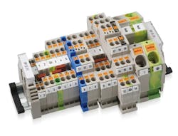
Insulated housings should be flame-retardant to meet UL 94 V0 and offer temperature resistance across a wide range from −40°C up to 120°C (Fig. 4). Conductive elements should be made from red copper (with 99.99% copper content) for the best conductivity and minimal temperature rise.

The quality of terminal block products is ensured by suppliers who test using laboratory facilities which are witness test certified by UL and VDE. Wiring technology and termination products must be rigorously tested in accordance with UL 1059 and IEC 60947-7 standards. These tests can include placing the products in ovens ranging from 70°C to 105°C for anywhere from seven hours to seven days depending on the test, and confirming that the heating causes no cracking, softening, deformation or melting. Not only must the physical appearance be maintained, but also the electrical properties. Another critical family of tests uses various types and durations of salt spray to determine a product’s long-term corrosion resistance.
Some manufacturers go even further beyond industry standards, creating accelerated aging tests to simulate harsh conditions and confirm a long product life. They choose high-performance materials like PA66 plastic, and they cultivate deep experience with high-accuracy injection molding processes to control all variables and meet end-user needs for miniaturized products that maintain all ratings.
Electrical terminal blocks are a basic component, but deserve some attention since they form the primary installation interface for electrical devices and wires. Traditional screw-type terminal blocks also are well known. Advancements such as PID and multi-level terminal blocks make it faster and easier to design, fabricate and service equipment while saving a significant amount of valuable control panel space.
Matt Hou is a sales engineer for Dinkle International and has been an integral part of the development of the Dinkle Corporation, USA subsidiary since 2018. He holds a BAS Degree in electrical engineering from the University of Waterloo in Canada.
About the Author
Matt Hou
Sales Engineer, Dinkle International
Matt Hou is a sales engineer for Dinkle International and has been an integral part of the development of the Dinkle Corporation, USA subsidiary since 2018. He holds a BAS Degree in electrical engineering from the University of Waterloo in Canada.
Voice Your Opinion!
To join the conversation, and become an exclusive member of Machine Design, create an account today!

Leaders relevant to this article: