Riding the Rails at a NASA Radar Range
This file type includes high resolution graphics and schematics when applicable.
The NASA Research Center in Hampton, Va., uses an indoor radar range to measure the radar cross-section (RCS) and antenna measurement range of very large objects. The RCS of a target is the effective area that intercepts the transmitted radar power and then scatters that power isotropically back to the radar receiver. The objects tested in the radar range can be quite large, such as the size of a plane, and the test-range field has the capability of analyzing multiple objects at the same time. The purpose of these tests is to help NASA design products that can either deflect or avoid radar detection.
NASA has contracted ADC USA Inc. to refurbish and upgrade its indoor radar range. ADC USA, located near Cornell University in Ithaca, N.Y., is a developer and supplier of complex high-precision motion systems and instruments for large government laboratories and corporations around the world. The radar range will include specialized active antennas, microwave circuits, and other electromagnetic devices. The orientation of the radar and target is a strong function of the RCS. Orienting the target—positioning it accurately within the radar range—is crucial to the measurement process. ADC built a transportation system in and out of the radar range that provided accurate positioning.
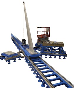
The positioning system that ADC developed used railroad tracks approximately 110 feet long that would be all metal welded. Two rails would be positioned about 4 ft. apart. They would traverse the distance to and through the indoor radar range. Picture a long railroad track inside a building that contains the 40’H × 40’W × 40’L range of the radar. NASA could roll equipment into the range and shoot it with radar to see what the radar looks like.
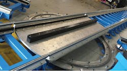
Because NASA wanted to put multiple targets inside the radar range without having to get a forklift to bring them in and out, ADC developed the design of a switching station outside the perimeter of the range. The switching station would actually be a turntable similar in operation to switching stations for railroad trains. Targets atop track sections could be moved on and off the turntable, which would then turn to align that track section with the 110-ft. long track that would bring them into the radar range.
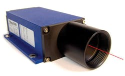
The Experimental Test Range rail system begins in the model prep area of the facility and ends 10 ft. past the center of the test chamber. The total length of the rail system is 112 ft. with laser position encoding for the final section of the rail system using the WayCon LLD-150-Profibus, which is accurate to 0.05 in. Linear guide rails are used to support the carriages and each carriage is positioned with a rack and pinion drive. Rails mount to steel weldments that are supported with 8-in.-diameter feet. Capacity of the rail system is 7,300 lb.
The design includes a place to dock positioning components when they are not in use. Curved linear guide rails support the switching station so that the platform can be rotated manually. Hardened tapered pins are used to align the switching station with mating rail segments.
NB Corporation of America machined the custom rails. They are case-hardened steel shafts (SFW 32 × 48 PD) that have tapered ends to improve transfer across the switching station platform. The rail diameter is 2 in. They are supported by NB shaft supports WA 32-48 PD, which are precision-machined aluminum extrusions available with or without pre-drilled mounting holes. They offer continuous shaft support and consistent shaft centerline. Spacing between sections is equal to the pitch of the rack so that transfer is completely motorized.
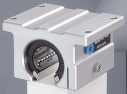
The NB Topball Slide Units chosen include a clear anodized corrosion-resistant aluminum block and a Topball self-aligning slide bushing. Closed and adjustable clearance styles incorporate machined snap ring grooves in combination with standard retaining rings for slide bush retention. Their open style incorporates bottom plates and mounting screws to retain bushings in the proper position.
Eric Van Every, director of operations for ADC USA, noted that designing the switching station was the hardest task. He said, “The one thing that had never been built this way is that switching station. That was unexpected. But, when I got into it, even talking to NB and talking to other vendors, no one has done something like that before.”
