The Back-and-Forth on Linear Motors
At a Glance:
- Linear motors can be described as uncurled 3-phase brushless servo motors laid flat. This definition decidedly overlooks their unique terminology, operation and design.
- An overview of three linear motors used for industrial applications: Flat, ironless (or U-channel) and linear shaft motors.
Belt and pulley, rack and pinion and lead/ballscrews have long been staples of linear motion, but each can introduce challenging limitations when machine builders look to increase the precision, speed and/or stroke length of an application.
Belt and pulley systems, while inexpensive and relatively quick, suffer in terms of settling time, positional accuracy and repeatability due to belt elasticity, especially as stroke length increases. Similarly, rack and pinion systems, exceptional for heavy loads and travel length, inherently offer slow accelerations. Lead screws, though inexpensive, are typically inefficient and also tend to degrade in performance as parts wear.
Precision ground ball screws provide the best all-round performance, in terms of efficiency, load capacity, minimal backlash and positional accuracy. However, increasing the speed of the system either requires increasing the thread pitch, while sacrificing resolution, or increasing the motor’s rotational speed at the risk of creating oscillation and vibration in the screw, especially at long stroke lengths. Whatever the solution, each will likely require a coupling plus a transmission and gear box, adding more points where the position reading at the motor’s rotary encoder can drift from the load’s actual position.
To overcome these limitations, machine designers turn to linear motors, especially for applications that require high throughput, exacting accuracy and/or aggressive motion profiles.
READ MORE: The Fine Art of Selecting Drive and Guidance Technology for Linear Units
To get a sense of the best linear motor use cases, it’s important to look first at how they function. The common description—an uncurled 3-phase brushless servo motor laid flat—is generally accurate but glosses over their unique terminology, operation and design. In place of a rotor and stator, for example, linear motors are composed of a forcer (containing electromagnetic copper coils) and a platen or base track (composed of multiple permanent magnets) that the forcer travels over or along.
The only physical contact between them is typically a mechanical bearing that maintains an air gap between the forcer and platen and supports the mass of the forcer plus the load attached to it. Due to minimal contact, linear motors experience very little physical wear and therefore require minimal lubrication or maintenance.
In fact, the elimination of power transmission components provides many of the technology’s benefits. Without couplings, gear boxes or other mechanical components, linear motors exhibit zero backlash and provide near instant settling times. This in turn allows for quick motion, typically enabling speeds up to 5+m/s or more and top acceleration between 5g to 10g. When combined with a linear encoder, linear motors also gain exceptionally high repeatability and precision down to the micron level in specialty applications.
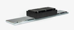
Flat Linear Motors
Of the various linear motor designs, three versions are used for industrial applications: Flat, ironless (or U-channel) and linear shaft motors. The most common, the slotted ironcore flat motor, is distinguished by a forcer composed of a comb-shaped backiron armature with laminated iron teeth around which the copper coils are wound. This configuration concentrates the coils’ magnetic flux and helps dissipate heat.
As a result, ironcore motors can generate the highest forces compared to other linear motor types and are designed for heavy load applications. For example, Kollmorgen’s brawniest ironcore motor, the IC44 line, supplies up to 6,673N of continuous force and 10,142N peak force without external cooling.
The trade-off for high forces, however, is often a loss of smooth motion. Like rotary motors, slotted ironcore motors can suffer from cogging, or jerking motion, as the teeth of the coil armature tend to gravitate to preferred positions along the permanent magnet track. In addition, the added mass of the iron forcer, plus its attractive force to the magnets, puts added stress and wear on the motor’s bearings.
To combat the cogging effect, manufacturers of ironcore motors often skew the orientation of the permanent magnets to make the transition from one magnet to the next less extreme. However, Brian Fink, product manager for Aerotech, admits it isn’t a perfect solution.
“Skewing the magnets does reduce the amount of parasitic motion from cogging, but it doesn’t eliminate it,” he says. “So, the motion is never going to be super smooth. If you have a process that requires really smooth motion, like a semiconductor lithography process for example, an ironless motor is a far better choice.”
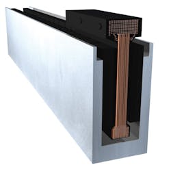
U-channel
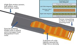
For applications that don’t require as high forces, U-channel, or ironless, linear motors offer exceptionally smooth motion and precision, Fink says. As its name suggests, ironless motors replace a slotted iron back plate with an I-beam shaped forcer around which the coils, potted in epoxy, are wound. Topped with an aluminum plate that acts as a heat sink and the attachment point for the load, the forcer rides within a U-shaped track with permanent magnets on either side.
Without the added mass (and inertia) of the iron forcer, U-channel linear motors eliminate cogging, reduce guide bearing wear and can achieve very high accelerations. Paired with a linear encoder, ironless motors also offer extreme precision.
READ MORE: Conveyance Systems in Robotics Maximize Efficiency
“An ironless linear motor stage is really the gold standard for applications requiring high dynamics, smooth motion and high precision,” Fink says. “When I say high precision, I’m talking about anywhere from a micron or two down to single digit nanometers. So very, very small level stuff.”
The trade-off for precision, smooth motion and high acceleration of U-channel motors, he notes, is typically reduced force density compared to ironcore motors. Manufacturers like Aerotech and others have designed ironless motors with more efficient copper winding geometries to boost force density. The company’s BLMX series motors, for example, offer a continuous force rating up to 1,063N and peak forces to 4,252N.
However, without the iron core, heat from the motor can propagate through the linear motor stage. In turn, this can cause small positioning errors, Fink warns, as the aluminum of the motor and steel bearings expand and contract at different rates. While the deviation between where the load is positioned and where the linear encoder reports it is may only be a few micrometers, the impact can be problematic for high-precision applications. Thermal management, Fink says, begins with correct motor sizing. Beyond that, engineers will need to look at external cooling options.
“Aerotech linear motors have a fitting designed into the end of them, where you can hook up a hose and pump forced air through it,” he explains. “It’ll go through the motor and cool the coils and reduce the effects of the heating. But then, now you need an air supply and you need to manage that hose.”
“There’s also an intermediate way to cool motors,” Fink adds. “The first place that heat will propagate is the stationary magnet track, so you can place a manifold with cross drills in it underneath or adjacent to the magnet tracks and run coolant through it. Now you’re not cooling the moving forcer; you’re cooling a stationary track. So, it’s a little easier to manage.”
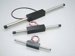
Linear Shaft Motor
For applications sensitive to the effects of heat propagation, linear shaft motors retain the motion dynamics, smooth motion and high precision of U-channel motors but with better heat dissipation, says Robert White, technical sales manager, Nippon Pulse America. That largely comes down to the efficiency of the motor’s design, he says.
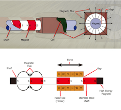
Unlike flat and U-channel motors, linear shaft motors are composed of a tubular metal shaft in which cylindrical rare earth magnets are stacked with like magnetic poles facing each other. The ironless forcer and its coils surround and travel along the permanent magnet shaft with a thin air gap between them.
This cylindrical design allows for the entire coil to interact with magnetic flux of shaft in all directions, rather than one side of the magnetic track as in a flat ironcore motor. As a result, shaft motors require less current, and generate less heat, to produce the same amount of force. In addition, a rectangular or cylindrical shaped forcer can also dissipate heat in all directions whereas heat can build up within a U-channel stationary track. Less heat means less potential thermal expansion and contraction, which translates to shaft motors’ exceptional accuracy, White says.
READ MORE: Fresh Off the Line: Six Product Rollouts to Level Up Your Engineering Toolkit
“With a linear shaft motor, you can get down to sub-nanometer and even picometer positioning capabilities,” he says. “It all depends on the feedback device, of course, and bearing systems. In some cases, the only way to get to that level is with an air bearing. But some of the good rails systems these days have really good performance. Every day, we’re selling product that uses half-micron encoders, and we’re getting micron, sub-micron positioning capabilities.”
The major limitation of linear shaft motors is stroke length. While an ironcore and U-channel motor can be as long as needed, White says the length of a shaft motor assembly is constrained since the tubular shaft is only supported at each end of the travel.
“With linear shaft motors, I can get maybe two meters, maybe three meters,” he says. “There are also techniques that you can do to make the shaft stay straight because you don’t want it to sag and touch the sides of the forcer. With shaft motors, I can’t go after eight- or 10 meter-type applications without doing something crazy.”
While each type of linear motor has its own unique strengths and weaknesses, there are a few challenges shared by all. For one, linear motors struggle with inclined or vertical applications since their rigidity is dependent on current flowing through the coils. If power is cut off, there’s nothing holding the forcer in place. Even when powered, linear motors in this orientation expend part of their force counteracting gravity. Manufacturers do offer counterbalancing and other mechanisms to offset this, but they can add complexity and cost to a project.
Linear motors are also more expensive than traditional mechanical linear motion. Even with the elimination of the power transmission components, linear can be 1.5 to twice as expensive as ballscrew-driven systems, depending on the complexity of the application. However, suppliers argue this higher initial cost is offset by decreased maintenance costs of linear motors plus the increased production that comes with their higher throughput and fewer rejected parts due to increased accuracy.

Ultimately, Aerotech’s Fink says the choice of technology comes down to the needs of the application and the role it’s looking to fill.
“If you’re looking at a ball screw versus linear motor, that’s going to be one of the earlier decisions in the engineering design process,” he says. “Both have their place, but it ultimately comes down to how you’re going to prioritize a couple of things, like motion performance, cost and complexity. Even within an application, it’ll depend on where customers want to enter the market. Is it a premium high precision application or more of a cost-effective player? We have the technologies that can span any of that. It’s just a matter of figuring out which one checks as many boxes as possible.”
About the Author

Mike McLeod
Senior Editor, Machine Design
Mike McLeod, senior editor of Machine Design, is an award-winning business and technology writer with more than 25 years of experience. He has covered the full spectrum of mechanical engineering, from industrial automation, aerospace and automotive, to CAD/CAE, additive manufacturing, linear motion and fluid power.
Voice Your Opinion!
To join the conversation, and become an exclusive member of Machine Design, create an account today!

Leaders relevant to this article: