A Practical Method for Estimating Moment Stiffness in Bolted Connections
What You’ll Learn:
- How to compute pitch moment stiffness of a bolted joint analytically.
- How strain cones and member deformation govern joint compliance.
- Which design levers most strongly increase moment stiffness.
- How to translate joint pitch stiffness into an equivalent linear stiffness to inform system-level performance.

Bolted joints are among the most common structural elements in precision machinery. They are used because they are strong, serviceable and reliable. Yet, despite their prevalence, the moment stiffness of bolted connections—especially under pitch or overturning loads—remains one of the least understood contributors to system accuracy and dynamic behavior.
Most design calculators and handbooks focus on axial stiffness or preload selection, but precision machine structures rarely experience pure axial loads. Instead, they experience a mix of axial, shear and, most importantly, moment loads generated by offsets between applied forces, structural interfaces and real-world system geometries. These moments can cause significant rotation, leading to positioning errors, reduced natural frequency and unexpected compliance.
READ MORE: Structural Properties of Bolted Joints
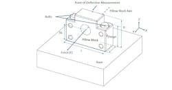
In a precision ball screw axis, for example, even a few micro-radians of angular deflection of the bearing support block can translate into measurable error. This is due to finite moment stiffness of the bolted interface of this bearing support block with the base plate (Figure 1). Similarly, in high-speed additive manufacturing machines, low moment stiffness can manifest as chatter, layer nonuniformity or servo instability. Understanding the fundamentals behind these behaviors is critical for engineers designing next-generation motion systems.
Why Moment Stiffness Behaves Differently Than Axial Stiffness
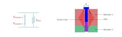
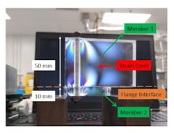
A bolted joint under axial load behaves relatively predictably: the bolt and clamped members act as springs in parallel (Figure 2). As the bolt is tightened, a strain cone forms beneath the bolt head and nut, which can be visualized using stress birefringence in transparent materials such as acrylic (Figure 3).
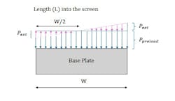
Under moment loading, however, the strain field becomes asymmetric. An overturning moment causes one side of the joint interface to enter compression while the opposite side unloads or separates, resulting in a non-uniform pressure distribution across the joint (Figure 4). This asymmetric deformation fundamentally changes how stiffness is generated and transmitted through the joint.
The Analytical Model Behind Moment Stiffness
Recent work by the authors1 developed a parametric analytical model that captures the coupled effects of bolt elasticity, member deformation, preload distribution and external constraints. The model predicts the rotational stiffness of a bolted flange—such as a ballscrew bearing support block—under pitch loads.
READ MORE: How External Loads Affect Bolted Joints
The key components of the model include:
- Bolt stiffness, modeled as a standard axial spring
- Member compression stiffness, governed by the effective compressed area under each bolt
- Offset between load line and interface, which creates the applied moment
The analytical model was validated against finite element analysis (FEA) and experiment, showing agreement within a few percent for steel blocks and 2 and 4 bolt patterns. For engineering teams, this means the model can be used as a fast design-space exploration tool long before detailed FEA is performed.
From a design perspective, the key insight is that pitch moment stiffness can be derived directly from the axial stiffness of the bolted joint and the effective width of the interface resisting the applied moment. This allows designers to estimate joint moment stiffness using quantities that are already familiar with axial joint analysis.
READ MORE: Bolted Joint Uncertainties
The pitch moment stiffness of the bolted connection can be approximated as:
Kmoment = KaxialW2/12
Where:
- Kmoment = Pitch moment stiffness of the bolted connection
- W = Width of the effective interface resisting rotation
- Kaxial = Axial stiffness of the bolted connection
When loads are applied at a height offset from the mounting surface, the resulting pitch rotation produces a linear displacement at the load line. To incorporate this effect into a system-level stiffness or accuracy budget, the pitch stiffness can be converted into an equivalent linear stiffness using the following. This conversion allows joint compliance to be treated consistently with other elastic elements in the drive system, such as the ball screw, bearings and support structure.
Kmoment(along the direction of force) = Kmoment/HcH = KaxialW2/12HcH
Where:
- Kmoment(along the direction of force) = Equivalent linear stiffness from moment loading
- Hc = Offset between load line and interface
- H = Offset between the displacement measurement point and interface
Design Takeaways for Improving Joint Moment Stiffness
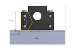
Designers can often achieve substantial improvements in joint moment stiffness with small geometric or layout changes—without increasing bolt preload or resorting to heavier structures (Figure 5). The following guidelines summarize the most effective levers identified by the analytical model and validated through simulation and experiment.
- Prioritize joint width over bolt preload. Pitch moment stiffness scales with the square of the effective joint width. Increasing the distance between the outermost bolts or widening the bearing block is typically far more effective than increasing axial stiffness and offers diminishing returns for moment resistance.
- Maximize bolt spacing in the direction of the applied moment. Bolts located farther from the neutral axis contribute disproportionately to moment stiffness. When packaging allows, spreading bolts along the load-resisting direction improves stiffness more efficiently than adding additional fasteners near the center.
- Account for clamped-member compliance, not just bolt stiffness. In most bearing block applications, member deformation dominates the joint’s rotational compliance. Treating the housing or base as rigid can significantly overestimate stiffness, particularly for lightweight or polymer components.
- Be cautious with low-modulus housing materials. Replacing steel housings with aluminum or polymer materials can reduce joint moment stiffness by an order of magnitude, even when bolt patterns remain unchanged. When lightweight materials are required, joint geometry must be adjusted to compensate for reduced modulus.
- Minimize load height above the joint interface. Angular deflection at the joint produces linear displacement proportional to the load height. Reducing the distance between the load line (e.g., ballscrew centerline) and the mounting interface directly reduces positioning error caused by joint rotation.
- Include joint moment stiffness early in accuracy and stiffness budgets. Joint-induced compliance is often comparable to or larger than ballscrew, bearing, or structural compliance. Incorporating joint moment stiffness early in the design process prevents unexpected accuracy loss and reduces the need for late-stage redesign or over-conservative structures.
Editor's Note: This article is based on work performed during co-author Akshay Dipakkumar Harlalka's affiliation with the Massachusetts Institute of Technology’s Precision Engineering Research Group.
Reference:
- Harlalka, A. D., and Slocum, A. H. An Analytical Model for Pitch Moment Stiffness of Bolted Connections and Its Application in Ballscrew Bearing Support Block Selection ASME Open J. Engineering ASME. January 2022 1 011027 doi: https://doi.org/10.1115/1.4054474
About the Author
Akshay Dipakkumar Harlalka
Staff Mechanical Design Engineer, Atomic Machines
Akshay Dipakkumar Harlalka is a staff mechanical design engineer at Atomic Machines where he works on development of precision machines for next-generation manufacturing of MEMS.
Alexander H. Slocum
Walter M. and A. Hazel May Professor of Mechanical Engineering, Massachusetts Institute of Technology
Alexander H. Slocum is a professor of mechanical engineering at MIT and a leading authority in development of precision machines, medical devices and renewable energy systems.
Voice Your Opinion!
To join the conversation, and become an exclusive member of Machine Design, create an account today!

Leaders relevant to this article: