A Guide to Applying Linear Handling Systems
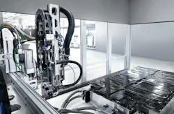
Linear handling systems and articulated robots, including collaborative models, are widely used platforms for automated motion. The engineering question is not which technology is better among them, but instead which solution fits the motion, the footprint and the economics of the application.
Linear Handling Systems
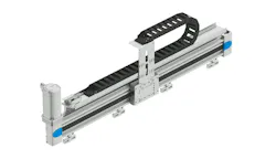
Linear handling systems are single- or multi-axis positioning platforms that move in straight-line paths. Unlike articulated robots, they rely on linear motion rather than serial rotary joints.
Linear handling systems are primarily applied in packaging, automotive and electronics manufacturing. Applications include pick-and-place, case packing, palletizing, machine tending, dispensing, pressing and inspection.
Examples help make concepts clearer. Consider the example of a high-speed case-packing line and the decisions involved in selecting a motion platform. Bottles arrive on a conveyor, are lifted vertically, transported horizontally and lowered into a case. The cycle repeats inside a rectangular work envelope.
A linear handling system aligns directly with these up/down and across motions. In linear systems, reach and payload are not mechanically coupled as they are in serial robots, so extending travel does not automatically force a move to a larger, more expensive robot model.
Because the envelope is rectangular and directly above the workspace, guarding and footprint can be tightly managed. Integration is typically handled through the PLC using motion instructions with which most controls engineers are familiar. Maintenance involves linear components that plant technicians service every day.
Consider selecting a cobot or six-axis industrial robot for this case packaging example. Serial kinematics enables flexible, fast deployment. As noted, reach and payload are coupled in robotic applications, so broad horizontal travel may require a larger, more expensive robot. Stiffness and positional accuracy may be an issue if the bottles and cases are near the edges of the robot’s work envelope where accuracy varies. Robots also generally require more space as well as beefier structural mounting frames.
In this case-packing example, dominated by straight up, straight across and straight down moves, a robot’s flexibility would be unnecessary. The larger safety envelope, coupled reach and payload sizing, and added programming and maintenance burden all indicate that a robot is not the optimum option.
A second example may challenge common assumptions. The first thing most engineers think about regarding palletizing applications that require flexibility and not hard automation is to apply a six-axis industrial robot. But consider the motion path: It is linear and similar to the case-packing example of up/down and across. When simple part reorientation is required, a discrete rotary module can be integrated without changing the fundamentally linear motion architecture.
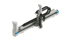
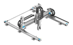
Because payload is not coupled with reach in a linear system, a less-expensive solution may work. A gantry palletizer is located directly over the workspace, allowing an optimal footprint. Gantry palletizers are not always the best option, but design engineers may have more choices than they realize.
If the application does not demand continuous reorientation or complex three-dimensional paths, a robot with a larger required safety envelope is likely the more expensive solution.
This is why decision criteria start with the motion profile, then footprint, then economics. Robots earn their place when orientation changes continuously or when motion paths are complex and three-dimensional. If the task demands that, a robot is usually the right answer.

Key Components of a Linear Handling System
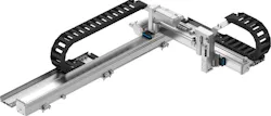
A linear system combines mechanical structure, motion components and accessories. Mechanically, it includes linear bearings, guide rails and belt, ball screw or lead screw drives. The carriage rides on the rails and carries the payload.
The motion layer consists of a stepper or servo motor and a drive. Motor-to-load inertia matching and dynamic force calculations determine whether the system performs reliably, avoids oscillation and achieves expected service life. Improper inertia matching can result in oscillation, reduced accuracy or premature wear. Accessories include energy chains, cable management, tow brackets and homing sensors.
The number of components in a linear system makes specification and assembly more involved than purchasing a robot that arrives with its control cabinet preassembled. Linear system components must be inventoried and available for deployment and field support, which adds logistical responsibility that should be considered during platform selection.
Build or Buy a Linear Handling System?
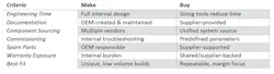
For years, many OEMs built their own linear systems. The supply infrastructure was not developed and often the exact size or load capacity wasn’t available.
Building a linear system also offered OEMs full control over capacity, footprint and aesthetics. Homegrown solutions fit established internal workflows. In some organizations, linear systems became a point of market differentiation. OEMs employed skilled technicians with years of experience assembling these systems and providing field support.
Sizing custom axes requires inertia calculations and iterative adjustments and precision mounting demands tight geometric control, especially when dual rails must remain parallel and flat over long strokes. These steps consume engineering hours that rarely appear in the initial cost comparison. Market conditions did not penalize OEMs then as they do today, given higher engineering and labor costs. Other cost factors included documentation for each machine, spare parts stocking and warranty exposure.
Changing Market Conditions Reduce the Advantages of Homegrown Systems
Today’s linear-system suppliers offer robust hardware plus sizing, configuration, procurement and commissioning support that many OEMs did not have when “build it yourself” was the default. The question is no longer whether suppliers can meet the specification; now engineers want to know how much friction can be removed from specification, assembly and support. Sales may be rising, but margins are shrinking.
One of the purposes of purchasing a linear system is to maintain or improve performance while expanding margin. The total cost of ownership, from engineering through lifecycle support, must be considered in order to see the full view of buy-it versus make-it. It’s trivial to examine the total cost of ownership (TCO) for a “home-grown” solution, but these calculations can be more challenging for a purchased solution. That is why supplier selection is critical.
On the hardware side, modern linear systems are engineered for repeatability and lifecycle durability, not one-off builds. Leading suppliers’ endurance test their products and provide life cycle data based on those results. OEMs typically cannot economically reproduce and publish performance data tied to reliability. A disciplined approach is to work with a small number of leading suppliers and obtain samples for lab validation. Then, test torsional tolerances to confirm performance claims. Evaluate whether the supplier offers a range of axis sizes to preserve platform flexibility.
OEMs must lower not only hardware costs but also engineering overhead to expand margins. Modern suppliers increasingly provide validated sizing tools that incorporate load, duty cycle and service life calculations to reduce the risk of under- or over-specification. These sizing and configuration tools must significantly reduce engineering time and produce optimized systems that can be ordered for serial machines as subassemblies or as kits.
Some suppliers also provide commissioning tools that further reduce integration effort. These steps reduce friction and lower internal costs. Suppliers must also demonstrate reliable technical support and spare parts continuity. Offloading these responsibilities contributes directly to margin protection and expansion.
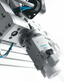
Modern suppliers have taken it a step further and also provide linear systems that are fully assembled and tested with all accessories included. These accessories include energy chain with support profiles, pre-wired sensor packages, grounding lugs and grounding cables, mounting kits and lifting lugs for hoisting. This enables linear systems to be “ready to install” right out of the shipping crate. The reduction of efforts from an engineering, procurement, assembly and testing standpoint is causing OEMs to turn to linear handling systems as a preferred solution for many automation tasks.
More content from Takeover Week: Automation & Robotics.
About the Author
 Cory Knight
Cory Knight
Business Development Manager, Festo
Cory Knight is a Business Development Manager at Festo, focusing on handling system projects in all industry segments. He worked as a machine design engineer for a decade before joining Festo.
Voice Your Opinion!
To join the conversation, and become an exclusive member of Machine Design, create an account today!
 Leaders Logo
Leaders relevant to this article: