Comparing Encoder Technologies
Encoders are widely used in the motion control and automation industry to monitor the position and speed of motors. This information can be used by the motion control electronics to detect if the motor and load are at the expected position and speed and to command corrective action if they are not.
Here’s a comparison of the six most commonly used types of encoders.
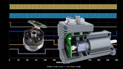
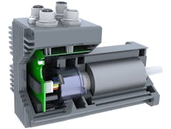
Optical Encoders
Optical encoders use the presence or absence of light to determine shaft position. There is a disk with slots in it that spins with the shaft. As the disc passes between a light source and a photoelectric sensor, the slots regularly let light pass through to the sensor or it blocks the light. The most accurate optical encoders use disks made of glass with black lines to block light on it created by precise photolithographic techniques. Lower resolution encoders use metal disks with stamped or etched slots.
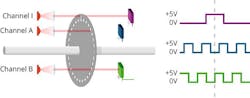
Standard optical encoders have two or more photosensors, offset by ½ slot pitch, which increases resolution through a technique called “quadrature decoding” which is built into most microcontrollers. Quadrature also lets the device determine which direction the shaft is turning. Quadrature decoding adds no lag and usually includes a digital filter to eliminate interference from electrical noise.
An encoder’s resolution is usually stated by the manufacturer in lines per turn or ppr (pulses per rev). This is the resolution of the raw A and B signals which are fed into a quadrature decoder to determine counts/turn, and counts/turn is the same as 4X lines/turn.
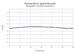
Optical encoders are typically available in resolutions from 128 to 20,000 counts/turn. Some larger models have higher resolutions. Typical accuracy is ±0.1 deg.
When encoders of any type are used as feedback devices in step-motor based configurations, resolution is important because the step motor’s high pole count results in a short electrical cycle. For example, a 1.8-deg. step motor has 50 electrical cycles per mechanical revolution and the difference between full torque and no torque is 1.8 deg. A 4,000 count/turn encoder provides 20 discreet counts over that 1.8 deg. of motion, which is enough to make stall detection, stall prevention and position maintenance possible. For real-time servo operations, a 20,000 count/turn encoder is a much better choice.
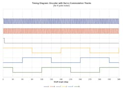
When applied to three-phase brushless motors, encoders often include three extra commutation signals (named U, V and W) that tell the driver when to switch current in the stator windings.
Optical encoders produce an immediate signal with no lag, so the shaft is where the encoder says it is in terms of position and time. Time is important when using the encoder to measure velocity and for real-time servo control.
Magnetic Encoders
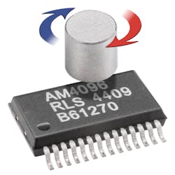
Magnetic encoders cost much less than optical versions and are more compact. Most use analog Hall effect devices mounted on a circuit board. The Hall devices are actuated by a two-pole magnet mounted on the end of a shaft. The Hall devices produce two out-of-phase AC signals with one cycle per shaft-turn. These signals are interpolated to create as many as 65,536 counts/turn. However, this interpolation is subject to many errors, such as electrical noise in the circuitry, imperfect magnetization, shaft runout, and radial and axial misalignment of the magnet. Most magnetic encoders include a way to calibrate them to offset as much error as possible.
Because magnetic encoders have one cycle per shaft-turn, they inherently measure absolute position within one shaft-turn.
Magnetic encoders always need time to interpolate signals. Early magnetic encoders had a variable (non-deterministic) conversion lag making them unsuitable for tracking real-time speed and position on high pole-count machines such as step motors. Newer encoders have predictable conversion lags. Knowing this, the CPU can automatically adjust position and velocity readings to compensate for lag.
Comparing Optical and Magnetic Encoders
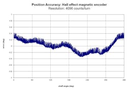
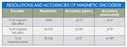
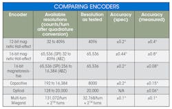
The first encoder is a widely used early 12-bit model that has proven to be reliable, low-cost and reasonably accurate. It includes an ABZ quadrature interface, providing 4,096 counts/turn, making it easy to work with quadrature encoder interface (QEI) modules common in microcontrollers and digital signal processors.
The 12-bit encoder was deemed unsuitable for some applications because its low resolution does not provide enough information for proper velocity regulation at low speeds.
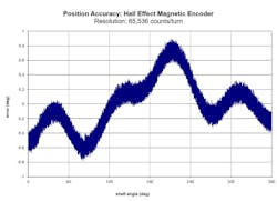
The second is a 16-bit magnetic encoder that uses Hall effect sensors. The resolution is much higher than the 12-bit model (65,536 counts/turn versus 4,096), but its accuracy is notably worse. This is due to several factors. First, the manufacturer’s calibration technique does not yield a small enough error. Second, its interpolation of Hall effect signals is inherently inaccurate. And third, the signal-to-noise ratio causes the count to vary by at least two bits even when not moving, which can create dithering and derivative noise in the servo loop. When evaluating an encoder, it is important to consider resolution and accuracy. Never assume a higher-resolution encoder is also more accurate.
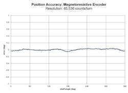
The third magnetic encoder uses magnetoresistive technology that is inherently more accurate and less sensitive to outside influences than Hall effect models. External magnetic fields, including those of the motor itself, can affect the operation of magnetic encoders.
This magnetic encoder offers a choice of ABZ or SPI (high-speed synchronous serial) interface. The SPI interface is common on DSP’s and microcontrollers and preferable to ABZ. But using SPI prevents sending an ABZ quadrature signal to another device (such as a motion controller) because the two interfaces share the same IC pins.
Capacitive Encoders
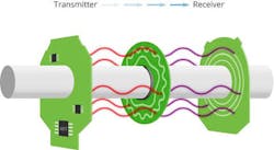
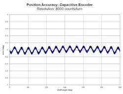
Capacitive encoders measure position by monitoring the change in capacitance in a circuit as the motor shaft turns. They are immune to external magnetic fields, as well as dust and debris. Capacitive encoders have resolutions up to 16,384 counts/turn (14 bits) and accuracy of ±0.2 deg.
Capacitive encoders provide a standard AB quadrature signal suitable for real-time use with most microcontrollers and most off-the-shelf drivers that include an encoder feedback option.
Capacitive encoders are more immune to electromagnetic interference than magnetic encoders and tolerate more contamination than optical types.
Multi-turn Encoders
Multi-turn encoders are useful for tracking shaft position while the controller or drive is turned off. For example, if a factory or technicians don’t want to rehome a system each time it is powered on, multi-turn absolute encoders are essential. (If it is only necessary to track position while the driver is powered on, the driver tracks position and a multi-turn encoder is not needed.)
There are three common types:
Battery backed multi-turn encoders use a battery to keep enough circuitry alive during power-down to track encoder position through several turns. The downside is that position information will be lost when the battery is depleted. The backup battery also tends to be large.
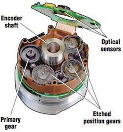
Geared encoders use a secondary encoder that moves by one or more counts each time the primary encoder completes one revolution. Geared encoders require no battery but are complex and costly, and the gears can wear over time.
Wiegand energy harvesting encoders use the Weigand effect to produce a pulse of electricity each time the encoder completes a turn. This energy is constant regardless of how slowly the shaft is turning when it passes a magnetic transition, so this pulse can reliably be used to power a small circuit and count the turns.
Wiegand encoders use a magnetic primary encoder that provides 131,072 counts/turn (also called 17-bit because 217 = 131,072). The turns counter is 16 bits, so it can track 216 = 65,536 shaft turns. Accuracy is ±0.1 deg.

The interface for Weigand encoders is often BISS-C. Few microcontrollers have a native BISS-C interface, so an external FPGA device is used to convert the signal.
Encoders are widely used in closed-loop motion applications. Choosing the best encoder for your application requires expertise, which can often be found behind the counter at encoder suppliers.
The Wiegand Effect
The Wiegand effect is a nonlinear magnetic effect named after its discoverer, John R. Wiegand. It occurs in specially annealed and hardened wire called Wiegand wire.
Wiegand wire is made out of low-carbon Vicalloy, a ferromagnetic alloy of cobalt, iron and vanadium. Initially, the wire is annealed. It is attracted to magnets and magnetic field lines are pulled into the wire. But the wire retains only a very small residual magnetic field when the external field is removed.
The wire is then twisted and untwisted to cold work the outside shell while the core remains soft. The wire is then aged. This makes the magnetic coercivity of the outside shell much higher than that of the inner core. The shell’s high coercivity lets it retain an external magnetic field even when the field's original source is removed.
The wire will now show a large magnetic hysteresis: If a magnet is brought near the wire, the high coercivity outer shell keeps the magnetic field from the inner soft core. But if the magnetic field rises above a specified threshold, the entire wire—both the outer shell and inner core—rapidly switches magnetization polarity. This switchover (Wiegand effect) happens in a few microseconds.
A Snapshot Encoder Comparison
- Optical encoders offer high resolution and are the most accurate. They are fairly immune to electromagnetic interference but are susceptible to contamination.
- Magnetic encoders are compact and low cost. They are susceptible to electromagnetic interference unless properly shielded. Resolution is good. Accuracy varies by manufacturer. Signal-to-noise ratios can reduce the usable resolution.
- Capacitive encoders are low cost and aren’t significantly affected by dirt, dust and electromagnetic interference. Accuracy is good.
- Multi-turn absolute encoders are useful when a load’s position must always be tracked, even when electrical power is removed from the system.
Jeff Kordik is chief technical officer at Applied Motion Products.
About the Author
Jeff Kordik
Chief Technology Officer
Voice Your Opinion!
To join the conversation, and become an exclusive member of Machine Design, create an account today!

Leaders relevant to this article: