Electromagnetic brakes and clutches
Clutches and brakes with an electromagnetic interface offer definite advantages, including accurate engaging and clean releasing. Besides being quick, they also run cooler and cleaner, with the convenience and controllability of electrical components. Here we take a look at the four general friction and non-friction types, how they work, and when they’re most appropriate.
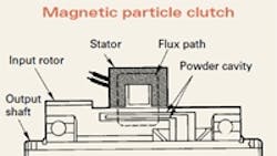
Magnetic particle
In magnetic particle brakes, an output disc (attached to the output shaft) sits untouched inside a housing. Remaining empty space within the housing is filled with magnetic shavings or powder that remains free-flowing until acted on by a magnetic field radiating from a stationary coil, embedded in the housing. When the coil is energized with dc power, the powder solidifies into chains along magnetic field lines, fixing the disc to the housing, and stopping the load. Only a few common materials show enough magnetism to do this effectively; these include iron, nickel, and chromium.
Less common magnetic particle clutches work in the same way; however, the stainless steel powder fills an empty space between a cup-shaped input rotor and an output shaft armature. A dc-energized coil in the housing locks these input and output devices together by magnetically exciting the powder between them; current induced in the rotor determines magnetic field strength and the amount of particle bonding, which in turn determines the amount of torque transmitted.
Magnetic particle clutches and brakes are infinitely adjustable making them particularly useful in tensioning and positioning applications where continuous changes of speed are required. Because they wear so little, these clutches and brakes are appropriate for synchronous and otherwise heat-inducing slip operation.
Hysteresis
In these clutches and brakes, hysteresis losses transmit constant torque for a given current. Used mostly in fractional power applications, they exhibit almost no wear. Brake units consist of a fixed magnetic pole assembly and a moving drag cup, which constitutes a rotor. The rotor is suspended by shaft bearings into a close-tolerance groove in the assembly; current applied to a coil in the pole structure creates a magnetic field in the groove. As the rotor turns, its magnetic particles do a constant flip-flopping in an attempt to stay magnetically aligned with the groove’s field. Braking resistance results from the hysteresis heat losses resulting from the molecular friction in the pole and rotor.
Though a slight eddy current effect is always present, full rated torque is independent of slip speed, the relative speed between rotor and pole assembly. During normal operation the rotor’s magnetic orientation is constantly realigned by its rotation and by coil current changes; this dynamic operation results in smooth transitions between torque levels for coil power adjustments. However, it is possible to set up a jumping pole condition on the brake rotor which results in pulsating cogging torque, also called torque ripple. It occurs when input current is greatly reduced and shaft rpm is low. Happily, this inherent hysteresis brake characteristic can usually be avoided or effectively controlled. Some units even feature automatic decogging.
Unlike brakes, hysteresis clutches have pole assembles that are free to move when driven. When magnetized, the drag cup’s specific hysteresis behavior supplies clutch linkage; hysteresis losses in the cup cause the flux to change more slowly through the cup than through the pole assembly. In this way, constant, smooth torque is transmitted through the drag cup as it is forced to rotate in the pole assembly groove.
In applications where electrical power can’t be supplied to a clutch or brake’s coil, permanent magnets can provide hysteresis braking. Permanent magnets are of hard magnetic materials with domains that stay in an aligned orientation, even in magnetic fields. By manually moving the magnets, the amount of magnetism acting on a brake’s output rotor can be adjusted. Also, because there are no electrical connections a brake unit can be used as a clutch. In this case, the pole assembly drives the rotor, and torque is transmitted through the magnetic air gap. These brakes and clutches are best suited to applications with fixed torques.
Continue on page 2
Eddy current
Eddy current clutches are almost structurally identical to hysteresis clutches. However, the output discs that rotate through induced magnetic fields are made of nonferrous materials — good conductors that are otherwise only marginally magnetic. Materials include repelling diamagnetic aluminum, weakly attractive paramagnetic copper, and brass. They typically exhibit good conduction and (more importantly here) good eddy current flow when subjected to a fluctuating magnetic field.
Here’s how they work: First, a clutch’s stationary field coil is energized, creating a magnetic flux that flows through the output rotor to the input drum. The motor-driven drum generates eddy currents and an associated magnetic field. This new field aligns with the magnetic fields in the pole assembly, which is weakened by counteracting eddy currents (and their associated I2R heat losses) that act as the retarding force. Thus, torque is created by slip.
During brake operation the rotor is made to rotate by a load. The stationary coil and pole assembly’s polewheel are fixed to the stator body, attached to the main housing. When the magnetic flux penetrates the rotor, an attraction is created between the stationary polewheel and rotor. Because the rotor is fixed to the output shaft, this attraction causes the output shaft to slow, and braking is established. This creates coupling torque proportional to coil current that disengages immediately and cleanly at separation. This torque can also remain constant at high temperatures.
Eddy current brakes are often used in applications that require high inertia masses to be stopped quickly; electric tramways and loading motors for testing are two examples. Eddy currents do generate I2R heating in the rotor, which limits usefulness. Drive applications best suited for these clutches and brakes are those where the lack of rotor and stator synchronization is acceptable, and constant output torque is desirable; they are frequently used in speedometers and tachometers. Optional tachogenerators are offered to feed linear speed signals to a controller for exact, closed loop braking.
Friction
A large number of electromagnetic brakes and clutches operate by friction. These use electrically created magnetism to clamp two friction faces together, thereby converting kinetic energy into thermal energy, which is then dissipated.
An electromagnetic friction brake consists of two principal components: an armature and a magnet. The armature is a steel plate or disc that is designed to rotate; it mounts to the shaft of the machine, and is the part clamped during braking. Often it is segmented to eliminate warping and to allow dissipation of wear particles and heat.
The magnet has three parts: a steel shell, a coil or wire, and a friction face. Applying power to the coil creates magnetism, which conducts to the shell and concentrates at the two poles. This pulls the armature plate against the poles to complete the magnetic circuit, forcing it into contact with the friction faces, and slowing its attached load. Friction faces are designed to dissipate heat and to spread magnetic clamping force evenly across the armature face.
Electromagnetic friction clutches are similar to brakes. However, clutches engage two shafts, in parallel or in-line configuration. Also, space between the coil and the friction face is required to transfer magnetism to a rotating piece.
A clutch consists of three components: an armature that mounts to the shaft, a rotor that mounts on the shaft next to the field without contacting it, and a magnet that contains the coil. When the coil is energized, the created magnetism jumps a small air gap between the field and the rotor, and concentrates at the rotor’s poles. The armature then engages the rotor poles like a brake; however, the armature turns with the rotating rotor.
Electric spring-set friction brakes are most common; dc power recompresses springs to release a friction plate connected to the shaft, allowing it to rotate. Electrically released permanent magnet friction brakes are also used. Permanent magnets on an electromagnetic friction brake’s steel shell clamp the unit’s halves together to stop and hold loads. Applying dc power to the coil creates a balancing magnetic field of opposite polarity that eliminates the magnetic attraction at the friction faces, and allows the armature to release and spin freely. An adjustable power supply keeps the two opposing magnetic fields in balance. Electromagnetic permanent magnet brakes capable of rapid stop-starting, and are not damaged by high cycle rates. However, they’re not appropriate for continuous slip operation, due to friction heat buildup. Friction brakes are often used as failsafe or holding brakes that engage when power is cut off.
Definition: electromagnetic brakes
Also called electric brakes, they are assemblies of electrical elements, activated by electric power, for the slowing or stopping of shafts in equipment drives. Types include friction, hysteresis, eddy current, and magnetic particle. Though only braking with an actual magnetic interface is discussed here, the term electromagnetic brake also refers to two other things. Here are the three definitions:
• A braking system whose force is supplied by an adjustable spring counteracted by a solenoid, a centrifugal thruster, and an actuator, in which the actuating force is supplied by current flowing through a solenoid or an electromagnet.
• An emergency braking system that is automatically applied to an electric-powered apparatus when a power failure occurs.
• The contact component of an electric braking system.
About the Author
Elisabeth Eitel
Elisabeth Eitel was a Senior Editor at Machine Design magazine until 2014. She has a B.S. in Mechanical Engineering from Fenn College at Cleveland State University.
Voice Your Opinion!
To join the conversation, and become an exclusive member of Machine Design, create an account today!

Leaders relevant to this article: