Why open-loop steppers lose steps, and how to solve the problem
In a perfect motion system, a motor turns a certain predetermined amount for every unit of electricity it is given. But if the load on the motor becomes too big, it doesn't matter how much power you try to feed it. Beyond a certain limit — maximum torque rating — motors can no longer turn. Motions become erratic, severely compromising accuracy. Why? Servo systems pick up on the resulting error right away, but open-loop systems don't. This is most troublesome when it appears in systems with stepping drive technology. Stepper systems are designed to provide position control without expensive feedback where precise motion is a requirement. Exceeding the available torque or other limits causes lost steps — failures to advance in position that go undetected.
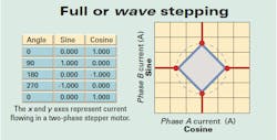
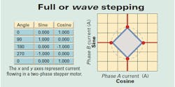
To move the motor, currents to the stator phase windings are varied so as to produce a rotating magnetic field. The rotor attempts to align itself with the magnetic field, following the rotation and producing motion. The high pole count of most stepper motors — 100 poles for a common 1.8° stepper motor — requires 50 full electrical rotations of the phase currents for one rotor rotation. The phase currents are driven with a sine-cosine signal approximation; that is, one phase is driven with an approximation of a sine wave while the other is driven with an approximation of a cosine signal.
When full-stepping a motor, there are four full steps per electrical rotation. These may be located either at 0, 90, 180, and 270° in the case of wave stepping (when one phase is on) or at 45, 135, 225, and 315° with two-phases-on stepping. Half-stepping produces eight steps per electrical rotation — every 45° — while microstepping ranges from 16 steps per revolution to hundreds or even thousands of points on each electrical rotation. In fact, as we'll discuss further, this is the capability on which “hybrid stepper” solutions to lost steps are based. A hybrid stepper motor is actually a high pole count ac synchronous permanent-magnet motor that may be operated down to zero frequency.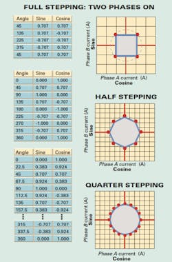
Resonance problems
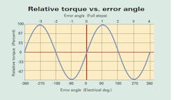
A motor produces torque only when its rotor is not aligned with the stator magnetic field. Torque varies in a roughly sinusoidal manner with this “error angle.” Two things in a motor combine to effectively form a non-linear spring/mass rotary pendulum:
• The interaction between the stepper motor stator field and the rotor.
• The rotor's moment of inertia.
Each step or fractional step applied to the motor windings shifts the equilibrium point of the pendulum, establishing a new error angle. The new error angle results in a new torque point, and the rotor — operating as a spring/mass rotary pendulum — attempts to follow. If the system is lightly damped (which is common) and the system is given enough time, the rotor overshoots the equilibrium point, ringing back and forth until it settles in. If the next step occurs when the system has sufficient speed while going in the opposite direction, then the peak instantaneous torque available may not be sufficient to keep the rotor within ±180 electrical degrees. When this occurs, the system slips into the adjacent cycle of the error-torque sine wave. When this happens the stepper, in effect, has just lost four steps. If the rotor is not able to regain synchronization with the stator, many more steps may be lost.
A rotor's ringing as a rotary pendulum — associated with dips in torque available from an open-loop stepper — is commonly called low-frequency resonance. The motor, applied current, and load all affect this resonant frequency, resulting in low-frequency resonance usually around 50 to 150 rpm, corresponding roughly to 150 to 500 steps per sec.
Stepper correction
Microstepping reduces the amplitude of the torque variations between steps, which reduces the excitation of the pendulum resonance, and thus the likelihood that the error angle will get large enough to lose steps. (Note microstepping is most effective with motors that have been optimized for it. To illustrate, many stepper motors optimized for full stepping have a detent torque that aids full-step positions, but actually causes significant cogging when microstepping.)
The resolution of microstepping drivers often drops as the rotational speed increases; the reduction in resolution is inevitable due to the limited bandwidth of both controller and driver. For argument's sake, imagine a designer attempted to operate a microstepping controller with 40,000 steps per sec at 50 rps (3,000 rpm.) It would then have to output 2,000,000 microsteps per sec to keep all the steps. Even if this were possible, a typical PWM driver only operates at 20 to 40 kHz — so the fine interpolations would never reach the motor. To address this inability to hit every microstep at higher speeds, the number of microsteps per second is often reduced as the motor speed increases. Transitions between these different resolutions can cause an impulse in torque to the motor, causing ringing that can result in lost steps.
Instability
There is another torque reduction that takes place at higher speeds, roughly corresponding to the speed at which the power-supply/driver combination becomes unable to control the current. This, in turn, corresponds to the start of the parabolic “constant power” portion of the torque curve, called mid-resonance instability. Loss of the ability to control current occurs when a motor's back-EMF rises to the point where power-supply voltage applied to the driver cannot overcome both the back-EMF and resistive and inductive drops at the requested current. The current undergoes a 90° phase lag from the commanded current as the driver switches from current control mode to voltage drive mode.
Any mechanical ringing of the rotor pendulum causes the motor to speed up and slow down, changing both the velocity and relative angle between the driven field angle and the rotor angle. This changes two things: the magnitude and angle of the back EMF with respect to the phase of the commanded current. Why does this matter? It can cause the driver to switch back and forth between voltage mode (full on) and current mode (chopping.) This can reduce the damping of the system, or even pump up the ringing until the rotor loses sync with the commanded position and loses steps, or stops spinning altogether. Operation in this speed region may require either mechanical damping or electrical damping to stabilize the operation of the motor to provide usable torque.
Sudden movements, external forces
Low-frequency resonance and mid-frequency instability are not the only ways to lose steps. The rotary pendulum is also set into swinging (in other words, becomes excited) by sudden changes in commanded velocity and load. Instabilities can also be mechanical. Shafts, couplings, and power transmission components between motor and load also act as rotary springs.
For example, gear trains release the load when changing direction, due to backlash. While the load is uncoupled from the system, the motor accelerates (because of lower inertia) until the backlash has been taken up. When the gears engage again, the difference in velocity between the motor and load can reflect excess torque back to the motor. Thus the system cycles: The motor slows below the speed of the load, again the load decouples, and then the motor speeds up. In some cases, the change in speed may be enough for the gears to first strike on one face and then rebound and strike on the opposite side, to repeat several times. The exact timing of the reversal ringing may vary with both the position of the gear train and with the wear of the gears, making it difficult to choose a stepping sequence that compensates.
A different stability issue arises with belt-driven linear movers. These units experience a resonance, the frequency of which constantly changes. As anyone who has ever played a stringed instrument (or a rubber band stretched across a cup) can attest, pitch or resonant frequency can be varied by changing either the string's tension or its length. The motion of a linear belt mechanism varies both of these. Linear force applied to the carrier and its load is the difference between the tensions of the two belt halves, while the position of the carrier varies the length of these belt sections. (Note that these same effects change both the resonance frequency of the belt itself, and that of the belt-load system.) This means that the same move with the same load and motor may work fine with the system starting at position A but not at position B. And what if the system carries a varying load? That only complicates the matter further.
Increasing stability
Both mechanical and electrical approaches are used to stabilize stepper motors. Mechanical approaches usually involve increasing motor rotary inertia to make load variations less significant, or adding damping to the system. Rotary inertia is increased either by swapping out the motor size or design, or by coupling flywheels to the motor shaft as close to the motor as possible. A system's mechanical damping is increased by including magnetic dampers, viscous inertial dampers, ferrofluid, and elastic motor mounts, couplers, and belts.
On the other hand, electronic approaches to increase stability typically measure (directly or indirectly) motor position and speed. Then current to motor windings is varied in a way that damps the system. These electronic methods include:
• Measuring or estimating the back EMF of each winding (which includes both speed and position information) and adding a portion of the back EMF signal into the commanded current at each winding
• Modifying driver circuits
• Using position/velocity information to modify the applied pulse train to the stepper motor
• Full servo control of the stepper motor.
More resources — for further reading
Leenhouts, Albert. Step Motor Design Handbook. Kingman: Litchfield Engineering Co., 1990.
Labriola, Don and Dan Jones. “Using Magnetic Gearing Performance from a Compact Integrated Servo.” Proc. of 28th Incremental Motion Control Systems and Devices. Lebanon: IMCSS, 1999.
Houda, Akihiko. “2-Phase Hybrid Stepping Motor with Keep-in-Step Control.” 28th Incremental Motion Control Systems & Devices.” Proc. of 28th Incremental Motion Control Systems and Devices. Lebanon: IMCSS, 1999.
Rusu, Calin. “DSP Based Control For the Hybrid Stepper Motor with Field Oriented.” Proc. of 28th Incremental Motion Control Systems and Devices. Lebanon: IMCSS, 1999.
Leenhouts, Albert. “Step Motors and Gear Play.” Proc. of 29th Incremental Motion Control Systems and Devices. Lebanon: IMCSS, 1998.
Nordquist, Jack. “Origins and Remedies for Resonant Activities in Step Motor Systems.” Proc. of 26th Incremental Motion Control Systems and Devices. Lebanon: IMCSS, 1997.
Raj, K., B. Moskowitz, J. Torres, D. Cooper, T. Burke, B. Trudeau. “Performance Characteristics of Ferrofluid Steppers.” Proc. of 23th Incremental Motion Control Systems and Devices. Lebanon: IMCSS, 1994.
Marushima, K. and Ralph Horber. “Development of a High Performance Sensorimotor with Sensor and Driving Coils.” Proc. of 23th Incremental Motion Control Systems and Devices. Lebanon: IMCSS, 1994.
Ohm, Dal, and Venkatesh Chava. “Torsional Resonance in Servo Systems and Digital Filters.” Proc. of 23th Incremental Motion Control Systems and Devices. Lebanon: IMCSS, 1994.
Kruse, David. “BLDC/Stepper Motor Controller for High Performance Incremental Motion.” Proc. of 22nd Incremental Motion Control Systems and Devices. Lebanon: IMCSS, 1993.
Bodson, Marc, John Chiasson, and Ronald Rekowski. “A State Feedback Tracking Controller for a Permanent Magnet Stepper Motor.” Proc. of 21st Incremental Motion Control Systems and Devices. Lebanon: IMCSS, 1992.
Jufer, Marcel, and G. Heine. “Hybrid Stepping Motors — 25 Years of Development.” Proc. of 25th Incremental Motion Control Systems and Devices. Lebanon: IMCSS, 1996.
About the Author
Donald Labriola, P.E.
President
Donald P. Labriola II, P.E., specializes in servo controllers and motors, with a special focus on cost-effective motion control. He has been granted ten U.S. patents as well as numerous international patents. His background includes over 35 years of motion control including 20 years in medical instrument design. He enjoys gardening, camping, and Ham radio — and motion control.
Labriola founded QuickSilver Controls in 1996. Prior to that, he worked at Beckman Instruments as a Senior Staff Electronic Engineer. Labriola earned his bachelor and master degrees from California State Polytechnic University, Pomona.
QuickSilver Controls Inc. (QCI) was founded in June 1996 to build Hybrid Servo actuators — actuatorse based on high-pole-count two-phase ac motors. Commonly known as microstep motors when operated open loop, their performance transforms when operated in closed loop. The PLC/indexer/servo control/digital drive are all combined into a single unit. QCI has expanded to now include three-phase brushless, voice coil, DC brush, linear hybrid servos, as well as the original rotary hybrid servo, and most recently the Mosolver — a hybrid servo actuator with a rugged low cost position sensor based on the same magnetic structure as is used by the motor.
In fact, QuickSilver products have been used in myriad applications from tracking drones to making tortillas, gluing picture frames, controlling animatronics, testing brakes on a fighter jet, processing semiconductors, controlling laser paths, and medical diagnostic and therapy applications, to name a few. The drive technology includes software and hybrid damping capabilities which allow the motors to be readily tuned to 100:1 inertial mismatch, frequently allowing for the elimination of gear heads via the resulting direct drive capability.
Machine Design articles including commentary from Labriola and coverage of QuickSilver:
New Product: Nema-11, 17, and 23 servocontroller/driver (2007)
The basics of system engineering: What system engineering is and what it does (2001)
Animatics, Quicksilver bury the hatchet, settle patent suit (2004)
All other QuickSilver mentions (2001 to Present)
Voice Your Opinion!
To join the conversation, and become an exclusive member of Machine Design, create an account today!

Leaders relevant to this article: