A new option for motor-position feedback: Built-in resolver design

All position-feedback devices for motor-driven machines have drawbacks. Encoders are usually rugged or inexpensive, but not both, and often necessitate expensive housings for industrial-level protection. Rotary encoders (optical and magnetic) have resolutions limited by the diameter of the disc and the width of the lines involved. Traditional resolvers are no better, because they need a dedicated excitation driver plus a hardware or software-based resolver-to-digital (R/D) converter (in addition to the resolver itself). They’re also “blind” for a portion of the electrical cycle — when drive voltage is near zero and sine and cosine winding outputs are at zero. Therefore, to feel through blind periods and estimate rotor position, resolvers use tracking R/D converters, which can degrade the phase-margin. Dual-driver resolvers address this problem but add cost for the drive electronics. In fact, for small motors, many feedback devices cost more than the motor itself. Options that don’t, such as Hall sensors, have temperature and resolution limitations.
Now, another position-feedback option in a combination motor-and-resolver design eliminates these problems with minimal materials and electronics. For the purposes of this article, we call the resulting feedback an emulated resolver, as the setup acts as a traditional resolver but without the rotary transformer or separate driver electronics. These sensors track motor position in two steps:
1. Emulated resolvers tap into the drive’s pulse-width modulation (PWM), normally used only to control the motor. Using sample windows that are synchronized to the PWM timing, they generate resolver-type sine and cosine signals.
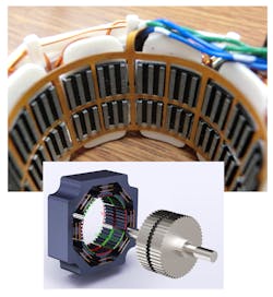
2. Emulated resolvers measure the changing magnetic paths that link the motor’s rotor and stator. To do this, they use dedicated sensor coils tucked into open space inside the motor. Motors that physically accommodate the sensor coils have lateral slots in the stator to let the coil wires pass across the faces of each pole structure without mechanical interference with the rotor. The sensor coils consist of a few turns of wire so the sensors cost less and are more compact than separate encoders or resolvers. The coils integrate into the motor, so they can’t become misaligned like other feedback elements — and the commutation signals are also inherently phased. Plus, the coils add only negligible weight and no rotor inertia.
Sharing the magnetic structure
PWM regulates effective voltage to the motor winding to control the torque producing current, but the chopping action also produces a by-product ripple current — a residual and periodic current variation normally undesired. In permanent-magnet motors, stator currents produce magnetic fields in the stator poles that interact with the rotor magnet. In some motors, the flux paths that link stator to rotor depend on the relative overlap of their teeth, and these overlaps change as the rotor turns relative to the stator. Flux variations (caused by ripple current) follow these same magnetic paths.
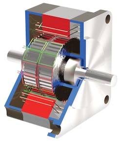
Consider a hybrid servomotor with the mechanical structure of a micro-stepping motor, but operating as a two-phase permanent-magnet ac-synchronous motor. Variants abound, but in one common design the rotor contains one axially polarized magnet sandwiched between two rotor caps made of magnetic-steel laminates. Typically the caps each have 50 teeth and are assembled on a shaft so the teeth of one align with the slots on the other. Then the assembly acts as a 100-pole rotor on any given stator tooth.
This 100-pole motor has 50 electrical cycles per one mechanical rotation of the rotor. Therefore, an emulated resolver on such a motor recovers 50 sine/cosine cycles/rev. These are absolute signals within the electrical cycle, so the controller sinusoidally driving the motor doesn’t have to prompt a “start-up wiggle” as it must for incremental encoders. Plus, the emulated resolver divides each electrical cycle into 640 counts (160 counts/90° quadrant of the sine-wave period) for 32,000 counts/rev, which is high enough to let the controls command smooth motion output.
What the coils measure
Let’s take a closer look at hybrid-servomotor operation to see what an emulated resolver measures. Typically, the stator has eight pole structures, each flaring inward with teeth facing the rotor and surrounded by a multiturn drive coil. Assume we number these pole structures 1 through 8 clockwise, starting at 12 o’clock. Vertical and horizontal pole structures 1, 3, 5, and 7 are “A” phases and diagonal pole structures 2, 4, 6, and 8 are “B” phases. The effective winding direction for 1 and 5 are the same, but the windings for 3 and 7 are reversed. Likewise, 2 and 6 are wound in the same sense but 4 and 8 are reversed. To minimize cogging, it’s best if groups of stator teeth don’t simultaneously align with the rotor teeth — so manufacturers build such motors with a stator tooth pitch either slightly smaller or larger than the rotor’s tooth pitch.
Now assume the rotor is positioned so its lower teeth align best with the teeth on the stator’s 1 and 5 structures and its upper teeth align with the teeth on the stator’s 3 and 7. Here, the motor is stable if the drive energizes phase A to produce north poles at 1 and 5 and south poles at 3 and 7. In contrast, if B is energized to produce north (N) poles at 2 and 6 and south (S) poles at 4 and 8, the (S) lower rotor teeth near 2 attract the (N) stator teeth and produce a clockwise torque. Repulsion of the (N) upper rotor teeth by the (N) stator teeth also produces a clockwise torque. In fact, a similar interaction takes place at 4, 6, and 8 to produce clockwise torque.
If the rotor can rotate but the stator windings aren’t commutated, the rotor turns one half-tooth clockwise and comes to rest. If the stator windings are varied to move stator attraction clockwise with respect to the rotor, the motor continues to spin. Reversing the offset reverses the torque.
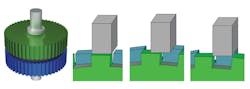
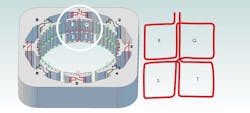
To understand the position sensing, consider how each pole structure in this example has six top teeth adjacent to the upper rotor cap and six bottom teeth adjacent to the lower rotor pole cap. The 12 teeth on each pole piece can be grouped into quadrants.
Emulated resolvers tap into the division of the flux between these quadrants caused by overlap of individual rotor and stator teeth that varies as the rotor rotates.
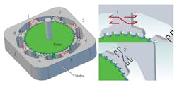
Group the eight stator-pole structures into four alternating quadrants Q, R, S, and T counterclockwise, so we add the coupling through quadrants Q and S and subtract the coupling through quadrants R and T. Then consider one stator-pole structure. (See image on page 67.) If the rotor is positioned so that the rotor teeth are in best alignment to upper stator teeth, they’re most poorly aligned to the lower stator teeth. The majority of the flux will pass through quadrants Q and R, with that through Q and R approximately equal, but less flux (though evenly divided) through S and T. When the flux changes due to the ripple current, the sense coil voltage produced by Q cancels that produced by R. Similarly for S and T, a zero net voltage is produced — Sin(0) = 0. With the rotor in this same position, consider the alignment of the adjacent pole structure, which is offset by 50/8 or 6.25 rotor poles. The 0.25 portion of this offset corresponds to one-half of a tooth width or 90 electrical degrees. The teeth of the rotor are shifted to the left by one-half step. Due to the difference in pitch between the rotor teeth and the stator teeth, the tooth alignment is better in Q and S than it is in R and T, causing the sensor to detect a maximal voltage when the winding is pulsed — Cos(0) = 1.
The resulting coupling of each sense coil alternates between positive and negative as the rotor turns.
The result is an effective coupling value that varies in a roughly sinusoidal way for A poles 1 and 5, as well as reverse-wound A poles (A* poles) 3 and 7. (We add signals from A* poles as they are twice inverted — once due to drive-winding reversal and once due to tooth offsets). The effect at the B and B* poles is similar, but follows a cosine variation with respect to the passing of each pole. These magnetic-coupling variations produce 50 sine and cosine cycles for each motor revolution.
Changing flux for output
To be clear, the sense coils don’t monitor back-EMF effect. Rather, the sense coils function as rotary variable-differential transformers that change output depending on motor position and the PWM drive’s excitation voltage. This allows good position sensing even when the rotor is stationary.
Reconsider our quadrants Q, R, S, and T. The overlap of the rotor and stator teeth changes as the rotor is moved, changing the magnetic couplings to the various quadrants. The emulated resolver tracks these electromagnetic couplings with a sensor coil as mentioned before — and the embedded controller times its measurements to synchronize with the voltage-producing flux variations caused by the PWM.
There are myriad ways to place the sensor and stator windings to sample the stator flux as modulated by rotor position. For example, it’s possible to use one sense coil for each phase. However, one of the most-effective setups is to have a sense coil on each stator pole piece to help compensate for mechanical runout in the rotor shafts and bearings. Multiple sensing coils also effectively eliminate the detection of motor back-EMF because there’s a net cancellation of back-EMF in the sensing coils as the rotor spins.
Assume we have a bipolar-chopper drive that uses PWM to vary stator flux. Whenever its circuit’s bridge drives a coil, the applied voltage rapidly changes current through its winding. Stator flux is proportional to the current through a winding multiplied by the coil’s number of turns. So the chopping action of the motor-drive circuit generates a ripple current — resulting in a time-varying flux for the emulated resolver’s sensor coil to detect. (The PWM action continues even when the motor is stopped.)
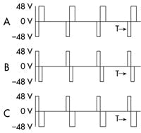
The PWM scheme uses gated antiphase chopping to modulate voltage to stator windings for good four-quadrant current control, even at near-zero current. Such a drive sends a short pulse to the winding opposing the drive voltage. Then it sends a longer (or equal) pulse in the direction of the target drive voltage. It applies a net-zero volt-second pulse if the positive and negative times are equal.
To let the emulated resolver use these signals, the drive controls coordinate the pulse edges so phase-B transitions don’t happen while the resolver takes measurements on phase A, and vice versa. Otherwise, unwanted transitions induce false signals on the sense coils during the read window.
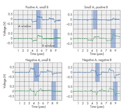
A PWM drive’s main function is to supply stator-winding currents to make the motor produce the right motion output. Usually controls use set parameters, control laws, and measurements (including those of target and actual positions and velocities) to calculate torque needed for making these moves as a function of time, subject to torque and velocity limits. While this is happening, though, the emulated resolver measures voltage near the end of every PWM cycle’s reverse pulse period and about 1 µsec later within the forward portion of the main pulse. The quick succession of these two readings emphasizes flux changes from the drive’s pulsing action and deemphasizes interference from flux changes from other effects that happen over longer time periods.
Getting good feedback
Emulated resolvers can give high-resolution feedback to myriad motors but are particularly useful in small motors for which high-resolution feedback is often expensive or impossible. Emulated-resolver resolution depends on the rotor and stator teeth accuracy as well as the a/d converter resolution. The sine-cosine outputs from the sense coils in the example motor yields a resolution of 32,000 counts per revolution with a background noise of about 1.6 counts RMS. The setup gets good measurements from 0 to 4,000 rpm with position sampling every 40 µsec (25 kHz) and none of the tracking delay of traditional sinusoidal resolvers. The readings all coordinate with the chopping drive so the transitions don’t cause noise but actually generate the position signal.
Edited by Elisabeth Eitel. Resources: QuickSilver Controls Inc.
Final note: Hybrid motor basics
Hybrid servomotors are based on high-pole-count permanent-magnet ac motors called microstepper motors when operated open loop. They have high continuous-torque ratings for their frame size and a high motor-quality factor (defined as the ratio of stationary torque to the square root of power). High torque capability means hybrid servomotors deliver full power over a wide range of speeds, from a few hundred to 4,000 rpm. That speed range means the motors pair well with belt drives and leadscrews (0.3 to 1-m leadscrews rated to a few hundred rpm to 1,500 rpm, for example) without needing gearheads. Put another way, a hybrid servomotor that outputs 100 W at 1,000 rpm can replace a conventional 500‑W servomotor with a flat torque curve and rated to 5,000 rpm. That’s because a typical 500‑W servo is typically only rated to one-fifth continuous power at one-fifth top speed (and Power = speed · torque.) Alternatively, a smaller 100-W, 5,000-rpm servomotor would need a gearhead to match it to the lower speed load — adding cost, weight, and size.
Hybrid servomotors incorporate less rare-earth magnet material than other options and are made in vast quantities, so they cost less. What’s more, traditional lower-pole-count ac servos typically use three to 10 times their continuous-rated current to produce similar torque densities but with heat that significantly reduces allowable duty cycle. On the other hand, conventional servomotors are available in myriad sizes, and some have better efficiency than hybrid servomotors for certain speed/torque ranges. Plus, they’re available with much higher speed ranges. In contrast, stepmotors run open loop are cheap but typically run with a higher input power than is required if running closed loop; the extra torque availability adds to system margins to avoid lost steps, but contributes to motor heating. Open-loop steppers also exhibit low and mid-speed resonances so are usually operated at only one-third to one-half their torque capability, and certain speeds may need to be avoided to prevent lost steps.
About the Author
Donald Labriola, P.E.
President
Donald P. Labriola II, P.E., specializes in servo controllers and motors, with a special focus on cost-effective motion control. He has been granted ten U.S. patents as well as numerous international patents. His background includes over 35 years of motion control including 20 years in medical instrument design. He enjoys gardening, camping, and Ham radio — and motion control.
Labriola founded QuickSilver Controls in 1996. Prior to that, he worked at Beckman Instruments as a Senior Staff Electronic Engineer. Labriola earned his bachelor and master degrees from California State Polytechnic University, Pomona.
QuickSilver Controls Inc. (QCI) was founded in June 1996 to build Hybrid Servo actuators — actuatorse based on high-pole-count two-phase ac motors. Commonly known as microstep motors when operated open loop, their performance transforms when operated in closed loop. The PLC/indexer/servo control/digital drive are all combined into a single unit. QCI has expanded to now include three-phase brushless, voice coil, DC brush, linear hybrid servos, as well as the original rotary hybrid servo, and most recently the Mosolver — a hybrid servo actuator with a rugged low cost position sensor based on the same magnetic structure as is used by the motor.
In fact, QuickSilver products have been used in myriad applications from tracking drones to making tortillas, gluing picture frames, controlling animatronics, testing brakes on a fighter jet, processing semiconductors, controlling laser paths, and medical diagnostic and therapy applications, to name a few. The drive technology includes software and hybrid damping capabilities which allow the motors to be readily tuned to 100:1 inertial mismatch, frequently allowing for the elimination of gear heads via the resulting direct drive capability.
Machine Design articles including commentary from Labriola and coverage of QuickSilver:
New Product: Nema-11, 17, and 23 servocontroller/driver (2007)
The basics of system engineering: What system engineering is and what it does (2001)
Animatics, Quicksilver bury the hatchet, settle patent suit (2004)
All other QuickSilver mentions (2001 to Present)
Voice Your Opinion!
To join the conversation, and become an exclusive member of Machine Design, create an account today!

Leaders relevant to this article: