A piezomotor is an electric motor leveraging the shape change that piezoelectric materials exhibit when an electric field is applied.
These often compact motors are suitable for myriad applications — offering better performance, efficiency, and miniaturization than conventional motors in everything from digital-camera focusing mechanisms, industrial valves, toys, and military applications. Four types exist.
1. Simple single-element piezomotors expand and output motion proportional to drive voltage.
They’re typically run at crystal resonant frequency. Tube versions are used in dispensing and scanning. Shear versions output high lateral force though limited travel, and can be set up for multi-axis operation. Fast-response stacked versions output high force.
2. Flexure-guided piezomotors operate like the simple type but incorporate motion amplifiers for longer, straight strokes — even to several mm.
3. Standing-wave piezomotors — also called ultrasonic piezomotors — can be made in linear or rotary versions.
Leveraging high-frequency oscillation of a stator, these exhibit unlimited motion, high speed, and fast response — to down to msec. Because motion is transmitted to a slide or rotor by friction, resolution is limited to 40 nm or so.
4. Piezo stepmotors cycle a series of crystals through different states.
The crystals are arranged in a “caterpillar legs” formation to allow for coordinated translation. These stepmotors can be designed for almost any range or stroke, with picometer resolution. Forces can exceed those of most other piezomotor types, beyond 100 lb in some cases.
• Rotary piezo stepmotors cycle their series of crystals (connected to either the motor’s casing or stator) through locked and motive modes. In short, one group of crystals is activated to lock an actuator rotor; a second crystal group is triggered and held to move a third free group of crystals forward. Then, the first crystal group followed by the moving group is released, retracting the third trailing group. Finally, both locking groups are returned to default.
• Linear piezo stepmotors also cycle their series of crystals (connected to either the motor’s casing or stator) through locked and motive modes. Typically, one set of crystals is in motive mode while two others cycle through locking; these push along the parallel surfaces by which they’re sandwiched to output linear motion. Quick crystal distortion (and hence, response) allows the steps to be made at frequencies exceeding MHz, for speeds to 100 cm per sec.
Q&A — How do rotary and linear ultrasonic piezomotors differ?
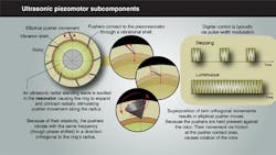
• In rotary ultrasonic piezomotors, pushers are attached to a piezoresonator through a vibrational shell. An ultrasonic radial standing wave is electrically excited in the resonator, causing a ring to radially expand and contract, stimulating pusher movement on the radius. Because of their elasticity, the pushers vibrate with the same frequency (though phase shifted) in a direction orthogonal to the ring’s radius. The superposition of the two orthogonal movements results in elliptical pusher movements. Because the pushers are spring-loaded against the rotor, their movement via friction at the pusher contact area causes rotor rotation.
• In linear ultrasonic piezomotors, piezo elements orthogonally bonded to a car produce vibration that rotates (and translates) an engaged screw for direct-drive linear actuation. Typically, two-channel sinusoidal or square wave is applied to the piezoelectric elements at an ultrasonic frequency in the kHz range, matching the first bending resonant frequency of the screw — for orbital motion that drives the screw.
What benefits do piezomotors offer?
• Piezomotors will never burn out, even if jammed while commanded to move; these motors exhibit high initial torque and a wide range of torques. The elimination of stick-slip (associated with some electromagnetic motors) allows full leveraging of a piezomotor’s quick start-stop capabilities. They can be normally locked or normally free; in the former, drift is negligible — less than 1 arc-sec/hour for some rotary types. Finally, electromagnetic motors must often be paired with gears and power-transmission components, and exhibit mechanical tolerances, backlash, and hysteresis. Piezomotors are direct-drive units, so offer higher resolution and repeatability.
• Power requirements are often simple, and controllers can be low-voltage units (less than 12 Vdc) enabling the use of piezomotors in mobile space and energy-constrained designs.
• Piezomotors are generally immune to electromagnetic interference, making them useful in MRI and similar applications.
Where are piezomotors used?
Piezoelectric motors are used in ultrasonic emitters, fertilization, micromonitoring, surgery robotics, pick-and-place, microdose dispensing, cell penetration and cell imaging in cytopathology, laser beam steering in dermatology and ophthalmology, and 3D scanning.
In certain unmanned drones, stacked piezomotors are integrated into the aerial vehicle’s morphing wing to supply hydraulic pressure to actuators. The design allows fluid to be confined to a closed loop surrounding each actuator, cutting fluid requirements, eliminating hydraulic lines, and removing weight.
In addition, piezomotors are leveraged in electronics and medical applications that involve focusing, scanning, adjustment, and inspection often use sub-micrometer positioning for their nm accuracy. For example, in a measuring application, piezomotors might power a linear actuator that slowly carries small objects past a sensor recording geometric data. Piezomotors alone aren’t appropriate, because most are limited in feed length and payload. In addition, these motors can take a long time to move parts into and out of a target “active measuring” area — particularly when gearing is incorporated to maintains the high resolution of low-speed moves. In contrast, when using a piezomotor plus a dc motor mounted on a common spindle, the dc drive can move the mechanism to target quickly (with its quick feed rate) and then the piezomotor delivers high motion resolution once it reaches that target.
Also read:
• The MICROMO Study Guide
• Piezomotors in actuators article
• Explanation of piezoelectric force sensors
About the Author
Elisabeth Eitel
Elisabeth Eitel was a Senior Editor at Machine Design magazine until 2014. She has a B.S. in Mechanical Engineering from Fenn College at Cleveland State University.
