Misconceptions about Stepper Motors Explained
Even veteran engineers often suffer from a lot of misconceptions about stepper motors and how to drive them. This article will focus on clearing up just a few of these misunderstandings so that engineers, both rookie and veteran, will have a little more confidence when selecting a driver. It would be great to cover everything, but then this article would turn into a 300-level university course.
In this article, we are talking about bipolar stepper motors as they are by far the most likely to be encountered by an engineer today. Unipolar steppers are still occasionally pressed into service, but their popularity has been on the decline for many years. You can still find them sometimes, usually inside devices like receipt printers. Precipitating this decline is the prevalence of inexpensive drivers for bipolar motors. Given the reduced cost of controlling the motor, why not use a bipolar stepper? After all, they can produce significantly more torque that an equivalently sized unipolar stepper.
Temperature
About a year ago, a pair of electrical engineers I worked with came to me. They were very concerned about the temperature of some stepper motors on a machine that I had built for calibrating parts in production. “How hot? Did you measure them?” I asked. As it turned out, no one measured anything. One of those guys leaned on a motor and felt the heat rolling off of it and assumed something was broken or malfunctioning. It took a thermocouple and the datasheet of the motor to prove to them that 80°C was well within the acceptable temperature range. Stepper motors typically run hot because there is multiple phenomena at work within them turning electricity to heat. Even when they aren’t rotating, they are subject to those same losses. However, when in doubt, check the temp. Repeatedly exceeding the max temp rating will, of course, destroy the motor. Or, more specifically, it will destroy the insulation inside the motor.

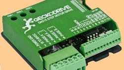
For situations where it is desirable to lower the average power consumption and consequently the temperature of the motor, there are drivers that will reduce the current draw during periods of inactivity. The Geckodrive GM215 driver at left has this feature.
Lower current correlates to less holding torque, though. This may be an issue if the braking effect of the motor is to be relied upon within an assembly.
Microstepping
Get a driver with microstepping, but don’t be taken in by high microstepping rates.
Microstepping is not magic. It can increase positional resolution, but it is gained at a significant expense in torque. Also, just because you have a driver than can do 1/32 microstepping doesn’t mean that your motor can. Beyond a certain point, about 1/10 or sometimes 1/16 microstepping, very high-quality motors and drivers are required. Even if your motor and driver pair are guaranteed to do 1/32 microstepping, will it work with the system it is meant to be part of?
Consider the following. A linear stage with a single-start, 10-thread-per-inch leadscrew directly coupled to a typical 200 step per revolution motor. Each full step of the motor will translate to 0.0005 in. of linear motion with one full revolution of the shaft translating to 0.100 in. of movement. It would appear, ostensibly that the same system with 1/32 microstepping will be capable of linear steps of about 0.000015 in. However, it is extremely unlikely that the elasticity and stiction in the system will allow those miniscule shaft rotations to translate into any movement of the linear stage at all.
Microstepping is going to really perform for you when you go to test a design, and the whole thing starts to shake or whine with noise. It gives you a variable to adjust to smooth out your system. Any mechanical system has a resonant frequency. For stepper motors, when this frequency is reached, usually at a particular speed, each step will “ring” like a bell. This ringing can result in missed steps that can turn into big problems for open-loop systems. It some cases, it can cause extremely violent vibrations. In the case of cutting machines like a desktop lathe or mill, this ringing can be seen as chatter on the surface of the work. Because microstepping shortens the shaft travel between steps, there is less energy to cause the ringing. Think of it as hitting the bell with a series of small hammer blows rather than swinging at it with full strength for each hit.
Rated Voltage vs. Power Supply Voltage
Perhaps one of the biggest points of confusion is the discrepancy between the coil voltage listed on a stepper motor’s datasheet and the usually much larger power supply used with it. If the datasheet lists a coil voltage of 3.4 volts, how is it that it can be used with a 48VDC power supply? Or an 80 volt power supply for that matter?
This is the deal. Ignore the voltage rating. Pay close attention to the current rating instead.
This can be done because most stepper motor drivers available are called chopper drives. These drives monitor the rise of the coil current and ignore the coil voltage. When the current gets to a predefined threshold (the maximum motor current), it shuts the power to the motor off. Or chops it. Don’t exceed the maximum voltage rating of your driver. That value is not a suggestion.
Take a look at the ratings given for this SparkFun stepper motor (part# ROB-09238):
Rated Voltage: 12V
Rated Current: 0.33A
Winding resistance: 32.6Ω
Winding inductance: 48 mH
The rated voltage of 12V is not a maximum value. What these ratings are actually saying is that if you apply 12 volts to a coil of this motor, it will set up a current of about 0.33A because the coil resistance is 32.6Ω.
If you are controlling a stepper with some H-bridges or a very simple type of driver, then you will have to limit the motor voltage to 12 volts to avoid exceeding the rated current, which is a maximum value.
In the case of a chopper drive, exceeding the rated voltage isn’t a problem. The higher voltage makes the motor reach magnetic saturation more quickly. The motor is strongest when fully saturated. The formula given below illustrates the point. It calculates the current through a coil after a given time frame:
Voltage * (tim /inductance) = coil current
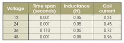
The current through a 50mH inductor over a time span of 1 millisecond increases proportionally with the applied voltage.
If the motor is being stepped before it can saturate enough to develop the needed torque, then it will start to lose steps. In fact, if you find that your motor is missing steps at speed, then get a higher voltage power supply.
Conclusion
As stated before, in no way is this article meant to comprehensively cover the subject of stepper motor control. But it does clear up some of the misapprehensions and at least one of the mysteries about driving stepper motors. A lot more study will be required on your part before you really start to develop a deep understanding of the topic. To get you started, the RepRap 3D printer Wiki has a lot of good information for the uninitiated. Geckodrive also has a very good primer on stepper motor control available in PDF format.

About the Author
Cabe Atwell
Engineer, Machinist, Maker, Writer. A graduate Electrical Engineer actively plying his expertise in the industry and at his company, Gunhead. When not designing/building, he creates a steady torrent of projects and content in the media world. Many of his projects and articles are online at element14 & SolidSmack, industry-focused work at EETimes & EDN, and offbeat articles at Make Magazine. Currently, you can find him hosting webinars and contributing to Penton’s Electronic Design and Machine Design.
Voice Your Opinion!
To join the conversation, and become an exclusive member of Machine Design, create an account today!

Leaders relevant to this article: