What’s the Difference Between Turbine Engines?
This file type includes high-resolution graphics and schematics when applicable.

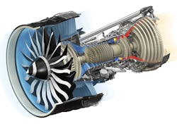
The gas turbine is one of the most widely used forms of propulsion systems for modern aircraft engines. The engine’s core—defined as the compressor, burner, and turbine—is also known as the gas generator, since the output is hot exhaust gas. The compressor and turbine are defined as the turbomachinery, where the energy is added or extracted from the continuous flow by the dynamic and aerodynamic action of rotating blades.
Common Parts of a Turbine Engine
Inlet
The inlet of the engine brings “free stream air” into the engine. The focus of an inlet is to decelerate the incoming air and convert its kinetic energy into static pressure.
• Subsonic inlets: Subsonic aircraft do not exceed the speed of sound. One can maximize the pressure rise by having either a longer diffuser or a higher diffuser divergence angle (diffuser area ratio).
The flow pattern for a subsonic inlet is divided into external (outside/upstream) and internal segments. External acceleration occurs for low-speed high thrust operation (i.e., takeoff conditions), which raises the inlet velocity and lowers the inlet pressure. Hence, the inlet area is designed to minimize external acceleration during takeoff so that external deceleration occurs during cruising conditions. On a typical subsonic inlet, the surface of the inlet is a continuous smooth curve that has some thickness from inside to outside. The inlet lip or the highlight, the most upstream portion of the inlet, is relatively thick.
• Supersonic inlets: Supersonic aircraft are still required to slow down the flow to subsonic speeds before the air reaches the compressor. The air flow has a Mach number between 0.4-0.7 when it reaches the engine face. Flow diffusion from supersonic to subsonic flow, also known as ram recovery, involves shocks. A normal shock inlet is the simplest supersonic diffuser. The shocks, which have a narrow inlet lip, are used for single normal shock (90° perpendicular to the flow) for Mach values less than 1.6.
Oblique shock inlets achieve higher total pressure recovery. Supersonic flow deceleration is achieved over a series of oblique shocks (a specific angle to the flow) followed by a weak normal shock. In an oblique shock, the supersonic flow is turned into itself; as the number of oblique shocks increase, the shock losses decrease, especially at high Mach numbers.
An axisymmetric external compression inlet is a cone-shaped diffuser that creates a conical shock. Due to the flow over the cone being inherently three-dimensional, the flow field between the shock and cone is no longer uniform. The effect results in a weaker shock wave than for a wedge of the same angle.
Compressor
Compressors are used to increase the air pressure before it enters the combustor.
• Centrifugal compressors: These compressors were implemented in the first jet engines, and are still used in turbojets and turboshaft engines. They turn the air flow perpendicular to the axis of rotation. The rotating impeller moves the air, which is collected in the scroll or volute. There may be a diffuser between the impeller and the volute.
• Axial compressors: Instead of a perpendicular flow, axial compressors flow the air parallel to the axis of rotation. The compressor consists of several rows of rotors and stators; which are a series of air foils. The rotors are connected to the central shaft and rotate at high speeds, imparting angular momentum to the fluid. Stators are fixed, which connect to the outer casing, increase the pressure while keeping the flow from spiraling around the axis by returning it to the parallel axis (acting as diffusers). Blade length and the annulus area decrease throughout the length of the compressor, reducing the flow area. This compensates for the increase in fluid density as it is compressed.
Burner
The burner or combustion chamber sits between the compressor and turbine arranged like an annulus. Here the fuel is mixed with high-pressure air and burned to create high temperature exhaust gas to turn the power turbine and produce thrust. A few of the desired properties of burners are to achieve complete combustion with minimum exhaust emissions, low total pressure loss, low heat loss from walls, and effective cooling. However, many of these properties compete with one another; hence, an optimal burner design is one of compromise.
• Can-annular combustors: Consisting of a series of cylindrical burners arranged around a common annulus, can-annular combustor chambers function independently of each other. At the entrance of each chamber is a diffuser that can reduce the velocity from a typical compressor outlet (100-150 m/s) to the bulk flow average velocity (20-30 m/s) in the combustion zone. It delivers the air to the combustion zone as a stable and uniformed flow field. This is an older design method for a burner.
• Annular combustors: A more modern design is an annular combustor. It is a single burner having an annular cross-section that supplies gas to the turbine. The combustion zone itself occupies an annular space. The improved combustion zone provides uniformity, design simplicity, reduced linear surface area, and a shorter system length.
Turbine
A turbine is like a compressor in that it consists of several rows of rotors and stators. The turbine stage begins with a stationary blade row called the nozzle guide vane, followed by a rotating blade row. The turbine converts thermal energy to kinetic energy by expanding through nozzles, then into rotational mechanical energy in a spinning rotor.
The flow in a turbine is dominated by favorable pressure gradients. Pressure changes can be quite large, and the boundary layers in a turbine are less susceptible to stall when compared to a compressor. Cooling of turbines is a major challenge; thus, they are designed to handle high temperature and corrosive environments.
Nozzle
The function of the nozzle is to convert the thermal energy into kinetic energy in order to obtain a high exhaust velocity. The nozzle thrust, or gross thrust, is comprised of the momentum and pressure thrust. A maximized gross thrust is when the nozzle is fully expanded or the ambient pressure equals the exhaust pressure.
• Subsonic nozzle: To accelerate a subsonic flow, the cross-section of a duct must decrease in the stream-wise direction. When the duct ends at the smallest cross-section, the result is a converging nozzle. The pressure at the exit of the nozzle is lower than the atmospheric pressure. As a result, the flow accelerates or expands to the atmospheric or local exit pressure. The higher the aircraft flies, the more velocity increases accordingly to the lower ambient atmospheric pressure. A limit is reached when the jet discharges at sonic velocity and the nozzle is said to be choked. Once the choked condition is realized, the nozzle mass flow rate is at its maximum and the conditions remain unchanged regardless of the decreases in ambient pressure. Hence, a converging nozzle can never produce a supersonic flow.
• Supersonic nozzle: For high exhaust velocities required for supersonic flight, a converging-diverging (CD) nozzle is used to create supersonic exhaust velocity. The CD nozzle construction consists of a convergent duct followed by a divergent duct. The cross-sectional area increase in the CD nozzle accelerates supersonic flow. A supersonic or CD nozzle requires a large pressure difference to accelerate the gas to a supersonic speed at the throat and further create supersonic flow in the diverging section of the CD. A significant pressure difference can be created by reducing the back pressure or the exit pressure of the surrounding downstream.
Adjustable nozzles allow a supersonic aircraft to match the varying conditions of ambient pressure and engine power settings for supersonic flight. And altitude adaptive nozzles can change the shape of the nozzle lip angle for optimal performance.
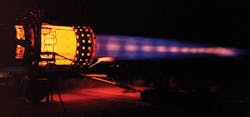
A problem arises when the nozzle is over-expanded or under-expanded. In an under-expanded condition, the pressure falls across the expansion waves and the exhaust plume expands past the nozzle exit, reducing efficiency in high altitudes. For over-expanded nozzles, the pressure rises across the oblique shock waves and a mixture of sub/supersonic flow. The exhaust plume is pinched by high ambient-air pressure, reducing its efficiency in low altitudes. Over-expansion can produce regions of complex wave patterns in the plume, which create a white/yellow luminescent glow as the low exhaust gas pressure tries to match the high ambient pressure.
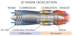
Turbojet Engine
The turbojet is the simplest type of gas turbine. Large amounts of surrounding air are pulled into the engine inlet due to the compressor. At the rear of the inlet, air enters the compressor. Pressure increases as the air passes the rows of blades. At the exit of the compressor section, the air pressure is higher than the free stream. In the burner section, fuel is combined with the air and ignited. The hot exhaust comes mostly from the surrounding air and passes through the turbine once it leaves the burner. The turbine extracts energy from the hot airflow by making the blades spin in the flow. In a jet engine, the energy extracted by the turbine turns the compressor by linking it and the turbine to the central shaft. The rest of the hot exhaust is used to produce thrust by increasing its velocity through the nozzle. Since the exit velocity is greater than the free stream, thrust is created. Very little fuel is added to the stream, so the exit mass flow is nearly equal to the free-stream mass flow.
Turboprop Engine
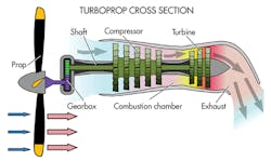
The two main parts for a turboprop propulsion system are the core engine and the propeller. The core engine is very similar to a turbojet except for the way it handles the energy from the exhaust. Instead of expanding the hot exhaust through the nozzle to produce thrust, the turboprop uses most of the energy from the exhaust to turn the turbine. An additional turbine stage may be connected to the drive shaft, which in turn is connected to the gearbox. The propeller connects to the gearbox, which produces most of the thrust.
The thrust produced from the exhaust velocity is low because most of the energy from the core exhaust is used to turn the drive shaft. Turboprop (and turbofan) engines usually have a two-spool engine where a separate turbine and shaft powers the fan and gear box, respectively. Turboprops are used only for low-speed aircraft like cargo planes. Propellers become less efficient as aircraft speed increases.
Turbofan Engine
Modern airlines use turbofan engines to propel their airplanes through the air. This is due to their high thrust and fuel efficiency. The turbofan engine is the most modern variation of the basic gas turbine. In the turbofan, two fans surround the core engine. One fan is in the front of the core engine and the other is located in the rear. The fan and fan turbine are connected to an additional fan shaft. The fan shaft passes through the core shaft in a two-spool engine arrangement. To achieve higher efficiency, some engines have additional spools.
The turbofan operates by capturing incoming air in the inlet. Some of the air passes through the fan, into the core compressor, and then the burner. The heat exhaust passes the through the core, fan turbines, and out the nozzle. This process mirrors that of a turbojet. The rest of the incoming air is redirected around the engine after it passes the fan. The air passing through the fan has a slightly higher velocity increased from the free stream.
The ratio of the air redirected around the engine versus the air that passes through the core is known as the bypass ratio. Low-bypass-ratio turbofans are more fuel efficient than the basic turbojet. A turbofan generates more thrust for nearly an equal amount of fuel used by the core because the fuel flow rate is changed by slightly when adding the fan. As a result, the turbofan offers high fuel efficiency.
The air passed through the core as well as the air passing around the engine comprise the thrust. Due to the fact that the inlet encloses the front fan and has many blades, it can operate efficiently at higher speeds than a simple propeller.
Afterburning Turbojet Engine
Afterburners are used in supersonic aircraft like the Concorde, and are turned off after achieving cruising velocity. Many modern fighter planes use a low-bypass-ratio turbofan equipped with afterburners for efficient cruising conditions and to produce high thrusts for dogfights, and on turbojets to fly at supersonic speeds, overcoming the sharp rise in drag near the speed of sound. The afterburner injects fuel directly into the hot exhaust. The nozzle of the basic turbojet becomes extended and a ring of flame holders is installed after the nozzle. Additional fuel is injected through the hoops and into the stream of the hot exhaust. The burning fuel produces extra thrust, but at an inefficient rate.
The burning fuel offers a simple mechanical way to augment thrust, but at an inefficient rate. The thrust calculation is the same as a normal turbojet, except that the exit thrust value is the thrust exiting the afterburner.
Thrust Equations:
FTurbojetor Afterburning Turbojet =á¹e â Ve – á¹FS â VFS
FTurboprop = á¹FS â (VPe – VFS) + á¹e â (Ve – VPe)
FTurbofan = á¹e â Ve – á¹FS â VFS + bpr â á¹c â Vf
where:
á¹FS = mass flow rate of the free stream of air
á¹e = mass flow rate of air at the exit of the core
á¹c = mass flow rate of the hot exhaust passing through the core
á¹f = mass flow rate of the fan flow or bypass flow
Vf = velocity of air at the exit of the fan
Ve = velocity of air at the exit of the core
VPe = velocity of air at the exit of the propeller
VFS = velocity of the free stream of air
Ve = velocity of air at the exit of the core
bpr = bypass ratio which equals á¹f/á¹c
Looking for parts? Go to SourceESB.
