Case study: Motion controls in semiconductor wire bonder
Wire bonding is how most modern integrated circuits are electrically connected, because it’s a cost-effective and flexible way to assemble semiconductor products. However, controlling the wire-bonding process is tricky — requiring high accelerations, short move and settle times, high accuracy, and high throughput. Bonding machines must weld delicate connections with wire — typically gold wire to 13 μm (0.5 mil) in diameter — at breakneck speeds.
How do they work? Bonding machines resemble sewing machines: Wire feeds through a disposable needle-like tool called a capillary to the semiconductor surface. First, the weld bead comes to the semiconductor surface (called the “pad”) in position-control mode. Next, sensors detect the weld bead touching the pad and switch the controller to force-control mode. Then heat, pressure, and ultrasonic energy weld each end of the wire. Once the bond is complete, the controls switch back to position-control mode and perform a coordinated X-Y-Z move to the next bond location.
The bonding machines that move the capillary tool around are three-axis systems with a bond head (Z-axis) coupled to an X-Y stage. The bond head assembly has a Z-axis voice coil with feedback resolution of 0.1 to 2 μm powered by a high-bandwidth (typically linear) amplifier for fast force response (and wire clamping and bonding accuracy better than 2 μm). The X-Y stage consists of linear three-phase dc brushless motors or voice coils with feedback resolution of 50 to 200 nm driven by PWM amplifiers for X-Y positioning accuracy of ±1 μm.
The best wire-bonding machines maximize throughput by welding 20 wires/sec. These need fast move and settle for the X, Y, and Z axes; profile times of a few milliseconds; acceleration of greater than 100 g and minimal settling time with no overshoot; coordinated X-Y-Z motion; high-volume data transfer between host, controller, and drive.
Likewise, the bonding head itself needs a current-loop bandwidth of greater than 3 kHz (for fast force response for wire clamping), a position-loop bandwidth greater than 200 Hz (for fast settling), low impact force, fast contact detection, and vibration suppression.
In one wire bonder, ACS Motion Control Inc., Eden Prairie, Minn., combines an SPiiPlusSC with an UDMlc and a UDMba. The SPiiPlusSC — a soft controller — is a PC-based (a.k.a. zero-footprint) controller that supports 64 fully coordinated axes and a 5-kHz update rate. The UDMlc is a lower-power four-axis drive that powers the bonding-head axis. It has an extra axis for non-demanding open-loop processes — such as opening and closing a shutter. The UDMba is a dual-axis drive that powers the XY stage.
EtherCAT control architecture (from Beckhoff Automation GmbH — read more about it here) lets ACS customize the wire-bonding machine and leverage high host-to-controller communication: The host application and SPiiPlusSC reside on the same PC, so shared memory and events facilitate ultra-fast communication. Competing solutions rely on Ethernet for this purpose, which creates a force-control bottleneck. The soft controller’s cycle time is as low as 0.2 msec for short move times plus smoother profile generation and feed-forward compensation.
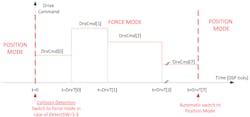
Algorithms also speed the wire-bonding process. Soft Touch force control quickly detects contact based on position error, drive command, or analog input (from a force transducer). Its nonlinear spring compensation, gravity compensation, and a damping mechanism limit impact force and suppress vibrations. After a collision is detected, force is applied based on a pre-defined timing diagram … after which the system switches back to position mode:
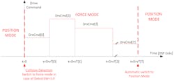
Transitions from position to force mode and back happen within 50 μsec.
ServoBoost (a servo algorithm) maximizes bandwidth and zeros settling time for sub-micron resolution; MotionBoost (a new motion-profile algorithm) minimizes settling time and maximizes dynamic performance. Motion profiles at the real-time servo update rate of 20 kHz smooth motion with durations even as low as 100 to 500 μsec. MotionBoost profile generation beats out second and third-order motion profiles by reducing drive current during aggressive moves — which in turn boosts throughput.
Thanks to Jason Goerges, General Manager, ACS Motion Control Inc. for the technical application submission. For more information, email [email protected] or call (763) 559-7669, extension 131.
About the Author
Elisabeth Eitel Blog
Elisabeth is Senior Editor of Machine Design magazine. She has a B.S. in Mechanical Engineering from Fenn College at Cleveland State University. Over the last decade, Elisabeth has worked as a technical writer — most recently as Chief Editor of Motion System Design magazine.
Voice Your Opinion!
To join the conversation, and become an exclusive member of Machine Design, create an account today!

Leaders relevant to this article: