Most writings on motion control have to do with digital control, but many applications still use analog servo loops. Analog and digital servo control actually have a lot in common. The main difference is that analog controls don’t have to deal with sampling, the process of running servo calculations at fixed intervals of time. Not having to sample removes delay, making analog controllers more responsive than their digital counterparts. Of course, analog controllers can be more difficult to adjust because servo gains are set with passive electrical components. Beyond that, though, digital and analog systems are quite similar.
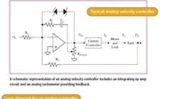
A typical analog proportional-integral (PI) velocity controller consists of an op amp and some passive components. The op amp plays the role of computer, executing the analog control algorithm. Resistors and capacitors determine the servo gains, and must be manually varied to tune system response.
Feedback in such a system usually comes from an analog tachometer. In general, the current controller and motor require the same considerations as those of a digital system (see Tune-Up, June 2000).
The loop diagram, shown here, resembles that of a digital PI loop with several additional scaling gains. One gain, for example, reflects the fact that the output of the servo loop is an analog voltage whose job is to command the current that drives the motor. The associated scaling constant, IPEAK/VPEAK, is measured in A/V. Another gain that’s required is the scaling constant for the tachometer, KTACH, which is measured in V/rpm.
Analog servo gains depend on the values of several resistors and a capacitor. The input resistor RC scales the command; likewise RT scales the tachometer feedback signal. The loop resistor RL is the key component in tuning the proportional gain, while the associated capacitor CL is the key to setting the integral gain.
Two zener diodes form a parallel loop, serving to clamp the gain of the integrator during large velocity swings. Without this “anti-windup” feature, the controller will continually integrate the error signal, producing large velocity swings and excessive overshoot.
Another important component is the scaling resistor RSCALE, a potentiometer that provides overall loop gain adjustment. Note that the scaling resistor is in line with the motor and load, modeled as KT/JT, where KT = motor constant and JT = total inertia (motor plus load). When inertia changes (as it often does) it can affect the loop gain as well as system performance. RSCALE compensates this effect, tuning it out to some extent. Of course, you could make the same sort of adjustment by changing RL and CL, but it’s less convenient because it may involve soldering in new components.
Tuning an analog PI controller is much like tuning a digital one. The trick is to work in zones as described in the June 2000 issue. PI controllers involve two zones, proportional and integral.
To begin, apply a velocity step command to the drive, making it as large as possible without calling for peak drive current. If you ask for too much current, you’ll saturate the current loops, making it more difficult to tune correctly. Step commands for tuning are ordinarily in the range of 50 to 500 rpm, depending on loop speed and the amount of inertia.
Now you’re ready to adjust the zones, starting with the proportional zone. First, zero the integral zone (short CL) and tune RL to get a little overshoot. Next, add in CL until the overshoot reaches about 15%. Remember to set the potentiometer away from the ends of travel, so you can use RSCALE to adjust performance if inertia varies up or down in the future.
Tune time
Want to tune an analog PI velocity controller yourself? Then log onto www.motionsystemdesign.com and download the most recent version of the ModelQ simulation program. Launch the program and select October’s model, then click “Run.”
This is the analog PI controller discussed above. The command (blue) and response (black) are overlaid, while the current is visible below. Usually it’s a good idea to monitor current while tuning to ensure the system stays out of saturation. Remember, if you have questions about constants, you can click on the button, “About this model....”
To tune the system, first tune Zone 1. Set CL = 0 and adjust RL to where the overshoot just starts to appear, then reduce it slightly. Here, overshoot occurs at 600 kΩ, so if you drop RL down to about 500 kΩ you shouldn’t see any overshoot.
Next, add in CL, always starting with a fairly large value. Remember that lower values of CL create larger servo gains. In this case, 0.01 μF achieves a good step response for a PI controller, about 15% overshoot.
After that’s done, reduce the load inertia by a factor of two. Notice how this degrades the performance of the system by causing it to ring.
Finally, adjust RSCALE down from 2 to 1 to account for the inertia change. On an actual amplifier, this would be done through a potentiometer. Notice how performance is restored, which is one of the key functions of RSCALE.
George Ellis is a senior scientist at Kollmorgen, Radford, Va. His latest book, “Control System Design Guide,” 2nd edition, was published in May, 2000 by Academic Press. He can be reached at [email protected].
