Why CAE Simulations Fail: Five Design Trade-offs Engineers Overlook

Computer-aided design (CAD) and computer-aided engineering (CAE) software allow engineers to design, simulate and iterate before building physical systems. These tools reduce development time and make it possible to evaluate designs earlier in the process.
Design decisions are increasingly made in the digital model, before a physical system exists. When those decisions are wrong, however, the failure is often not discovered until validation or production.
The working assumption is that a digital model can predict how a system will behave once it is built. That assumption holds within limits.
Every model depends on input data, simplified physics and defined conditions. These choices make analysis possible, but they also introduce gaps between the digital representation and the physical system.
When those gaps are not accounted for, the impact appears late. Mechanisms bind, structures deflect beyond expectations and systems require rework to meet performance targets.
The following five tradeoffs define where CAE support effective design decisions and where they introduce risk.
1. Model Speed and Iteration vs. Input Data Accuracy
CAD and CAE tools allow engineers to move quickly from concept to analysis. Designs can be modified, simulated and evaluated in rapid cycles, reducing reliance on physical prototypes.
This speed assumes that the data used in the model—material properties, loads, boundary conditions and constraints—accurately represent the real system.
READ MORE: “CAE Automation: From AI Prompt to Simulation”
In practice, input data is often incomplete or estimated. Material properties may not reflect manufacturing variation. Loads may be oversimplified. Boundary conditions may not fully represent how the system will be constrained in operation.
A model can produce results that appear valid even when inputs are inaccurate. A component may meet strength requirements in simulation but fail under actual loading.
The issue often surfaces during validation, when designs require rework, additional analysis or delayed testing.
Effective use of CAE requires treating input data as a design variable, not a constant. Identify and validate critical assumptions early. Where data is uncertain, evaluate designs across a defined range of conditions or include margin to account for variation.
If inputs are estimated or incomplete, results should be treated as assumptions, not validation.
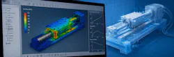
2. Simplified Modeling vs. Real-World Complexity
A design that performs in simulation can fail once real-world interactions are introduced.
CAD and CAE tools reduce complex systems into manageable models. Loads are defined, constraints are applied and interactions are simplified so that analysis can be performed efficiently.
The assumption is that a simplified model captures the behavior that determines system performance. This is not a data accuracy issue. It is a modeling choice—what is included in the analysis and what is left out.
Key interactions may be excluded. Contact conditions are idealized, friction is treated as a constant and assemblies are represented without the full effects of tolerance stack-up. Thermal expansion, vibration and multi-axis loading are often simplified or omitted.
For example, a linear guide system may meet load capacity requirements in simulation but bind under combined loading and slight misalignment once assembled.
Engineers are then forced into late-stage corrections—modifying geometry, adding compliance or redesigning interfaces to address behaviors that were not evaluated.
Effective use of CAE requires identifying where interactions matter. Critical effects—such as contact, alignment and thermal behavior—should be evaluated explicitly when they influence performance. If they are not modeled, designs must include margin or be validated through targeted testing.
If key interactions are not modeled, the design must be validated physically before release.
3. Clear Output vs. False Confidence in Results
A simulation can be precise and still be wrong. CAD and CAE tools produce results that are clear and easy to interpret. Stress plots, deformation maps and animations present complex behavior in a simplified visual form.
The assumption is that a consistent and well-defined result reflects actual system behavior. In practice, results often reflect only the conditions that were defined. Load cases may be limited, boundary conditions simplified and operating scenarios incomplete.
READ MORE: CAD Automation: Manual Design Workflows Don’t Scale
The issue is not incorrect data or missing physics. It is incomplete evaluation. The model may be internally correct but externally incomplete.
For example, a bracket designed to support a static load may pass simulation with acceptable stress levels. When exposed to combined loading and vibration in operation, fatigue cracking can occur at stress concentrations not evaluated in the original model.
The problem often emerges when designs that pass simulation encounter operating conditions that were never evaluated.
Effective use of CAE requires defining the full range of conditions the system will experience. Engineers should test sensitivity by varying loads, boundary conditions and material properties. If small changes produce large differences in outcomes, the design should not be considered validated.
If the evaluated conditions do not match real operating conditions, the results are not reliable.

4. Digital Model Fidelity vs. Physical System Variability
A design that performs within limits in a digital model may not perform consistently across physical builds.
CAE models represent systems with precise geometry, defined material properties and controlled conditions. Dimensions are exact, components are aligned and behavior is consistent.
The assumption is that a high-fidelity model reflects how the system will behave in production.
In practice, physical systems vary. Manufacturing introduces tolerances that affect fit and alignment. Materials behave differently depending on processing and operating conditions. Wear, contamination and environmental factors change performance over time.
READ MORE: AI is my CAD Co-Pilot
Assemblies built within tolerance limits do not behave identically.
A shaft and bearing system designed to nominal dimensions may operate smoothly in simulation but exhibit vibration or uneven wear in production due to tolerance stack-up and alignment variation.
The result is often greater performance variation, increased testing effort and reduced predictability in production systems.
Effective use of CAE requires designing for variation, not just nominal performance. Engineers should evaluate sensitivity to tolerance stack-up, material variation and environmental conditions.
If performance changes significantly within expected tolerances, the design is not robust enough for production.
5. Faster Iteration Cycles vs. Reduced Validation Depth
More iteration does not produce a better design.
CAD and CAE tools allow rapid design cycles. Engineers can modify geometry, rerun simulations and evaluate multiple options in a short time.
The assumption is that increased iteration improves design quality.
In practice, faster iteration can reduce validation depth. Designs are updated quickly but not always tested under a full range of operating conditions. Simulation replaces some physical testing, but not all failure modes.
A design may pass multiple simulation cycles and still fail during physical testing or early production, where combined loading, extended use or environmental conditions reveal issues not previously evaluated.
The impact appears when designs that have been iterated extensively still require validation-driven redesign.
Effective use of CAD and CAE requires separating iteration speed from validation depth. Critical conditions—such as worst-case loads, extended cycles and environmental exposure—must be defined and tested regardless of iteration speed.
If worst-case conditions have not been tested, the design is not complete.
CAD and CAE tools remain essential because they allow engineers to evaluate designs earlier, reduce development time, and explore more design options before physical testing begins. But every digital model reflects assumptions about data, physics, operating conditions and system behavior.
Effective engineering requires understanding where those assumptions introduce uncertainty and where physical validation is still necessary. The goal is not to eliminate tradeoffs, but to identify where simulation supports confident decisions and where additional validation is required before release.
More content from Special Focus: CAD/CAM/CAE.
About the Author
Steve Sterling
Steve Sterling is a Minnesota-based freelance writer and editor.
Voice Your Opinion!
To join the conversation, and become an exclusive member of Machine Design, create an account today!
 Leaders Logo
Leaders relevant to this article: