How AI-Driven Design Tools Are Missing the Mechanical Reality of Robotics
Introduction: The Appeal of the Generated Design
AI has arrived in the mechanical design studio, and its promises are hard to resist. Give a generative tool your load cases, and in minutes it returns organic, optimized shapes no human would draw. Describe a motion in plain language and an AI assistant suggests a mechanism. Upload a bracket and the software hands back a lighter one that still passes the same analysis.
These tools are useful and they are here to stay. Modern packages are also far more capable than their early versions; the good ones now handle fatigue, multiple load cases and manufacturing rules such as draft angle and tool access. The trouble is rarely that the tool lacks the ability. It is that someone has to set the ability up correctly. This step is often skipped under deadline pressure and even done well, it still does not reach the system-level and soft-material behavior that decides whether a robot actually works.
That is the gap this article is about. AI tools are great at the parts of the problem you can write down cleanly: cut mass, add stiffness, fit a model to data. They are weakest where the goal is hard to put into an equation: how tolerances add up across an assembly, how a mechanism behaves at full speed, how a system drifts as it heats up over a shift and how a material moves when it will not hold still.
These failures are not the algorithm’s fault. They are framing failures and framing is still the engineer’s job.
What the Optimizer Solves and What It Skips
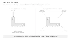
Every optimizer solves the problem you give it, and the mistake is rarely in the math. It is in how the problem was set up. A tool told to make a part stiff under one static load will do exactly that and do it well. What it will not tell you is that this single load case may represent only a small slice of the part’s real life.
A robot linkage never sees just one static load. It sees a load that changes constantly with position, speed and acceleration, repeated millions of times. The stress that matters is not the single peak case. It is the fatigue built up over the whole cycle. An optimizer that was never shown this full history will happily cut material from the very spots that fatigue attacks because under the static case those spots looked lightly loaded.
READ MORE: Robotics Readiness Checklist: 6 Things to Ask Before Implementation
It is worth being precise here because the tools are better than the criticism usually admits. Fatigue-aware and multi-load optimization does exist in modern packages, and the capability is real. But it has to be set up deliberately, with a load history the engineer builds by hand.
Under schedule pressure, that history is often reduced to a single static case. The variables that actually govern reliability, repeated loading, resonance, wear, heat and assembly stress, are the hardest to express as an objective function. So they get left out, whether or not the tool could have accepted them.
The Blind Spot: Making it and Building it
The most eye-catching output of generative design is the organic, bone-like shape that looks impossible to machine. These shapes look great in slides. They often cannot be made at a sensible cost, put together by a technician or serviced in the field.
A generative tool rewards saving material. It has no built-in sense of the flat face a fixture needs to grip, the straight bore a bearing needs, the clearance a wrench needs or the draft a casting needs to leave its mold. Unless you spell these out as rules, and most workflows spell out only some of them, the tool gives you a shape that needs heavy rework before it can be built. The time you saved in the software gets spent, often with interest, making the result buildable.
Assembly is another blind spot. A robot is not one clever part. It is dozens of parts that must go together in order, absorb real-world variation and come apart again for repair. Optimizing each part alone can produce pieces that are locally perfect but do not fit together. Two brackets each pass every check, but you cannot install one without removing a third part that was optimized on its own. The tool never saw the assembly, so it could not protect it.
Tolerance Reality: The Stack-up No Model Sees
Maybe the biggest gap between AI design and real hardware is tolerance. In a model, every dimension is exact and every surface is perfect. In production, every dimension varies a little and those small variations add up through the mechanism.
A four-bar linkage built to exact numbers traces a clean path in CAD. Built from real parts, every pin, bore and link length varies within its allowed band, and the gaps at each joint add play. The real path is a smear, not a line. The width of that smear decides whether the mechanism hits its target. Optimizing the shape of each link does nothing for this, because the error comes from how the tolerances combine across the assembly, not from any single part.
This is where the AI workflow quietly makes things worse. Generative tools optimize one component at a time, each against its own local objective, and they are happy to hand back a set of individually optimized parts. But tolerance is an assembly-level property. The dimension chain that decides whether the mechanism hits its target runs across parts, through joints the optimizer never modeled together.
A tool that produces four separately optimized links has, if anything, less coherent control of that chain than a human who designed the linkage as a single system with the stack-up in mind. The optimization is real; it is just aimed at the wrong level.
Generative tools optimize one component at a time, each against its own local objective, and they are happy to hand back a set of individually optimized parts. But tolerance is an assembly-level property.
The order of magnitude is easy to work out. A four-bar has four pin joints and each normal clearance fit adds a few hundredths of a millimeter of play, on top of link-length tolerances of roughly ±0.05 mm. Every one of these is small and well inside its drawing limit, but they do not cancel. Joint gaps show up as lost motion, link errors propagate through the linkage and both grow at the positions where the mechanism trades speed for reduced mechanical advantage.
A favorable combination still lands around one to two tenths of a millimeter at the tip; an unfavorable one pushes it higher. For a job with a 0.1 mm placement budget, the mechanism can fail on tolerance alone, before any heat or motion effect enters the picture. The optimizer that trimmed each link’s weight while holding its nominal length told you none of this, because the number that mattered, the total variation at the output, was never in its objective.
Good designers handle this by instinct. They find the chain of dimensions that matters most, put the tight tolerances only where they count, add adjustment where variation cannot be avoided and set up datums that control how error spreads. These calls need an understanding of how the mechanism must work and how it will be built. That is a whole-system judgment today’s tools do not have. A tool that optimizes parts one at a time cannot manage a stack-up it never saw.
Dynamic Behavior: Where Static Models Go Quiet
A robot arm speeding through its workspace is a moving, connected system. Its links flex, its drive parts give a little, its structure has natural frequencies and all of that together produces the real motion at the tip. Most AI design tools work on static or near-static models. They can tell you a part is stiff. They cannot tell you it will shake at a multiple of your cycle rate and rattle your gripper at the exact spot where accuracy matters.
This matters because “stiff” and “well-behaved” are not the same thing. A part optimized only for static stiffness may put its natural frequencies in a bad range or pile up mass where it hurts the motion most. The optimizer, blind to the moving duty cycle, has no reason to avoid this. It hands you a stiff part that happens to behave badly in motion, and you find out during commissioning, when fixing it is expensive.
Getting motion right means treating the mechanism as a moving system: understanding how its inertia shifts through the cycle and placing its natural frequencies on purpose. This is ordinary, well-established engineering. It just sits almost entirely outside what today’s generative tools try to optimize.
Thermal Blindness: The Drift the Model Never Saw
Robots run for hours and they heat up while they do. Motors dissipate heat, bearings add friction and the structure itself expands. A part that an optimizer shaped for minimum mass and maximum stiffness at room temperature can quietly drift once the machine reaches steady-state heat a couple of hours into a shift and the optimizer had no reason to see it coming.
The geometry is part of the problem. When a topology optimizer removes material, it leaves thin webs and uneven cross-sections that heat and cool at different rates than the bulk around them. Those gradients bend the part.
READ MORE: What High-Mix, Low-Volume Automation Really Requires
A lightweight optimized arm can hold position perfectly in a cold check and then walk a few tenths of a millimeter off target as it warms, simply because the mass was placed for stiffness, not for thermal stability. On a system with a sub-millimeter placement budget, a drift of that size is the difference between passing and failing. It shows up only after the machine has run long enough that no one is watching for it.
Coupled thermomechanical optimization does exist in the better tools. But it is slow to run; it needs a time-based duty cycle that is tedious to set up and it is one of the first things dropped when a deadline looms. In practice the thermal dimension gets assumed away, no matter what the tool can technically do. The result is a design that is right on day one at hour zero and slowly less right as it warms—a failure that is invisible in the software and very visible on the floor.
The Hardest Case: Soft Goods and Bending Materials
If moving rigid parts already push past what most AI tools model, soft materials are completely out of reach. A rigid link has a fixed shape. Its behavior, however messy, is at least bounded. A shirt, a towel, a cable or a plastic bag has almost endless ways to bend. Its shape at any moment depends on its history, its condition, friction, static cling, humidity and exactly how it was last grabbed. There is no clean formula an optimizer can hold and no fast, trustworthy simulation of a crumpled shirt settling under gravity.
This is why handling soft goods is still one of the most unpredictable problems in robotics, and why so much consumer robotics continues to focus on tasks like folding laundry. Folding a towel looks easy to a person, yet it has become an unofficial benchmark precisely because it beats the tools we trust most. The vision system cannot fully predict how the cloth will fall, the planner cannot list every possible shape and no design tool can produce a gripper that guarantees the same grip on something that never looks the same twice.
Learned methods have made real progress and recent systems fold cloth far better than just a few years ago. Yet companies often demonstrate one carefully staged towel under ideal lighting conditions. Performing the task reliably across any garment, any speed and any condition is a different challenge, and one that remains far from solved in the messy real world.
Folding a towel looks easy to a person, yet it has become an unofficial benchmark precisely because it beats the tools we trust most.
The lesson is broader: The more a task depends on the unpredictable state of the object rather than the shape of the robot, the less an AI tool can help. The hard part is not designing the mechanism. It is dealing with a physical reality that resists being written down. Engineers who work on high-speed handling of soft materials learn this the hard way.
The mechanism that wins is rarely the most elegant one. It is the one whose designer understood how the material really behaves under grip, tension and speed. That understanding does not come from an optimizer. It comes from watching real material fail in real machines.
The Counterargument: Physics-Informed and Surrogate Models
A sharp reader will point out that the frontier is moving straight toward these gaps. Physics-informed neural networks build the governing rules, Newton’s laws, beam theory and dynamics right into the model, so it cannot wander far from real physics. Machine-learned surrogate models trained on high-quality simulation can copy dynamic, thermal and fatigue results fast enough to use inside an optimization loop. These are exactly the methods aimed at teaching design tools the physics they now ignore, and they are promising. I have written about their potential elsewhere.
But promising is not the same as trustworthy in production, and that gap matters most in the fast, safety-critical systems this article is about. A physics-informed model is only as good as the physics it was given and the range it was trained on. Push it into conditions it never saw and it can be confidently wrong. A surrogate trained on simulation carries every shortcut of that simulation, including the ones nobody noticed. Proof remains the hard wall.
Showing that a learned model will behave correctly across the full range of a machine running millions of cycles is far more difficult than validating a conventional mechanism whose limits can be calculated on paper. These methods will likely close some of the gaps sooner than skeptics expect. They have not closed them yet and treating them as if they have is its own kind of framing mistake.
What Engineers Still Have to Bring
None of this is an argument against AI design tools. Used well, they do things no human workflow can match. A generative tool can try thousands of lattice and shape options in the time an engineer sketches three, turning up light structures no one would think of. Surrogate models can stand in for a slow simulation closely enough to turn an overnight run into a real-time slider. These are not just conveniences. They change what is worth attempting. The argument is not against the tools. It is against handing your judgment over to them.
The engineer’s lasting job is framing the problem: deciding which load cases matter, which tolerances are critical, which resonances have to be avoided, how the parts go together, how the thing gets serviced and how it behaves after two hours of running. These are the judgment calls that decide whether a robot works in practice, and they are precisely the ones today’s tools cannot make because they require understanding of the mechanism as a physical object operating in a real factory.
A good workflow uses AI where it shines and human judgment where it cannot be replaced.
In the systems I have worked on, the failure was rarely the part the optimizer touched. It was the interface it never saw: the tolerance chain across an assembly, the resonance that only showed up at full speed, the drift that appeared two hours into a shift, the material that would not behave the way the model assumed. The geometry was fine. The reality around the geometry was the problem.
A good workflow uses AI where it shines and human judgment where it cannot be replaced. Let the tool explore shapes inside limits the engineer sets from a full-system view. Let it propose options and let the engineer check them against the manufacturing, tolerance, motion and heat realities the tool cannot see.
The tool proposes. The engineer decides. Flip that around, treat the generated design as the final word and the engineer as a rubber stamp and you get designs that are perfect on paper and broken in practice.
Conclusion: Reality is Still the Final Judge
The physical world is unforgiving in a way software is not. A design either survives its fatigue or it cracks. It either goes together or it does not. It either holds tolerance or it drifts. It either avoids its resonances or it shakes. No amount of clever generation changes the fact that the real world tests every design against limits the model may never have included.
AI design tools are widening what engineers can do, and that is genuinely valuable. But they extend engineering judgment; they do not replace it. The tools optimize what they can see. The engineer owns everything they cannot: the motion, heat, tolerance and manufacturing realities that decide whether a robot runs or just renders. As these tools get better, the engineer’s most important skill becomes knowing exactly what the tool is not telling you and supplying it.
That is the mechanical reality today’s AI design tools are missing. Not the shape, which they draw beautifully, but the physics of the whole life that shape has to survive.
More content from Takeover Week: Automation & Robotics.
About the Author
 Santosh Yadav
 Santosh Yadav
Hardware Development Engineer, Amazon Robotics
Santosh Yadav is a Hardware Development Engineer at Amazon Robotics and an IEEE Senior Member. He holds multiple US patents on deterministic kinematic synchronization and publishes monthly in Machine Design on mechanism-centric approaches to industrial automation.
Voice Your Opinion!
To join the conversation, and become an exclusive member of Machine Design, create an account today!
 Leaders Logo
Leaders relevant to this article: