Why Replacement Gears Can Fail Even When Dimensions Match
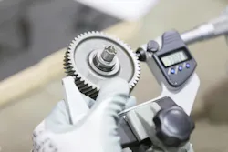
A replacement gear can match the original part in diameter, bore, face width and tooth count and still perform poorly once installed. It may run noisily, the contact pattern may shift toward one edge or backlash may fall outside the expected range. In more severe cases, the replacement may develop rapid wear, pitting or tooth damage even though a dimensional inspection shows no obvious problem. The reason is that dimensional similarity does not automatically mean functional interchangeability.
Matching the basic envelope and mounting dimensions is not the same as reproducing the complete tooth geometry and operating mesh. A gear operates as part of a system. Its performance depends not only on visible dimensions, but also on tooth geometry, the mating gear, center distance, backlash, alignment, material condition, heat treatment, surface finish and the actual loads carried by the drive.
For replacement work, the important question is therefore not simply, “Does the new gear have the same dimensions?” but rather, “Will the new gear reproduce the same operating relationship with the rest of the transmission?”
A Dimensional Match is Only the First Check
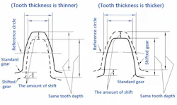
While basic dimensions are still important, those measurements describe only part of the component. Two gears can appear nearly identical with a caliper and still differ in tooth geometry in ways that affect how they mesh. The same tooth count and outside diameter do not by themselves confirm that two gears have the same pressure angle, tooth thickness, profile modification or manufacturing reference geometry.
Pressure angle, for example, affects the direction of force transmitted between mating teeth. If the replacement gear uses a different pressure angle from the mating gear, the teeth may not contact as intended even if tooth count and nominal diameter appear compatible. Possible consequences include abnormal contact, increased noise and concentrated loading.
Similarly, a replacement gear may measure correctly in several external dimensions but still produce too little or too much backlash because its tooth thickness or reference geometry differs from the original. The effect may not become obvious until the gears are mounted at the real center distance.
In addition, the theoretical involute profile is not always the complete finished geometry. Depending on the application, the original gear may include profile relief, tip relief or other modifications intended to improve meshing under load. A replacement made without reproducing those features may look dimensionally correct but behave differently when torque is applied.
Likewise, gears may also include crowning, lead correction or end relief across the face width. These modifications can compensate for shaft deflection, bearing movement or housing deformation. If the original design used a modified flank but the replacement is manufactured as a simple unmodified geometry, the load may become concentrated near one side of the tooth face. The difference may be difficult to see without appropriate measurement, but its effect can become clear in the contact pattern.
The Mating Gear Changes the Equation
A replacement gear never operates against an ideal theoretical counterpart. It operates against the actual mating gear already in the machine.
If the mating gear has been in service for thousands of hours, its tooth profile and surface condition may have changed. It may show polishing, pitting, localized wear, profile deterioration, edge wear or a different surface condition from when it was new.
A new replacement gear running against this worn surface does not begin service under the same conditions as the original pair did when both components were new. The worn mating gear may shift the contact pattern or reduce the effective area carrying the load.
This creates an important replacement decision: Should only the failed gear be changed, or should the mating member also be replaced? There is no universal answer, but the mating gear should always be inspected before assuming that replacing one component will restore the original mesh.
A new gear installed against a severely worn mating gear can reproduce the same abnormal contact condition that contributed to the previous failure.
Why Backlash May Change After Replacement
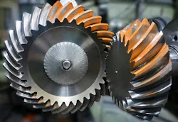
Backlash is a system measurement rather than just a property of one gear. It depends on the relationship between two mating gears and their assembled position. Important influences include tooth thickness, center distance, bearing position, shaft location, housing geometry, temperature and wear on both gears. This explains why a replacement gear can meet its individual drawing dimensions and still produce unexpected backlash after installation.
If backlash is too small, thermal growth or operating deflection may further reduce clearance. If it is too large, reversing or shock-loaded drives may experience greater impact as load transfers between opposite flanks.
An abnormal backlash value should therefore not immediately be interpreted as proof that the replacement gear was manufactured incorrectly. The complete assembly should be checked, including center distance, bearings, shaft position and the condition of the mating gear.
Contact Pattern Reveals what Dimensions Cannot
One of the most useful checks in replacement gear work is the tooth contact pattern. A dimensional report tells whether specific measurable features are within specified limits. A contact pattern shows how the pair actually interacts.
The intended contact region depends on the gear design and application, but excessively concentrated contact near one edge, tip or root can indicate a problem that individual measurements may not reveal. An abnormal pattern may point toward shaft misalignment, center-distance error, bearing movement, housing distortion, incorrect tooth geometry, unsuitable flank modification or a worn mating gear.
This is particularly important in heavy-duty drives. When torque is applied, shafts bend, bearings move slightly and housings deform. A gear pair that appears acceptable during an unloaded hand check may develop a different contact condition under operating load.
Conditions that Make a Correct Gear Look Wrong
Sometimes the replacement gear is not the problem at all. Wear on bearings, shaft deflection or housing movement can change the relative position of the gears. If this shifts the mesh toward one edge of the face width, the local load rises.
The replacement gear may then begin to show edge polishing, localized pitting, higher noise, elevated temperature or accelerated surface wear. Replacing the gear again will not correct the condition if the shaft and bearing system remains unchanged.
Before blaming the replacement component, inspect bearing clearance and condition, shaft runout where relevant, mounting surfaces, housing condition, coupling forces and shaft alignment. This is especially important when the previous gear failed with a strongly localized wear pattern. The pattern may be evidence of a system condition that was already present before the new gear was installed.
Material Selection, Hardness and Finish
Material selection and heat treatment also influence how the tooth surface and core respond to repeated loading. Depending on the application, relevant factors may include steel grade, surface hardness, core hardness, case depth, micro-structure, material cleanliness, residual stresses and surface integrity after finishing.
Surface hardness is often checked because it is relatively easy to measure. But equal hardness values do not necessarily mean two gears have equivalent material condition. For example, two carburized gears may show similar surface hardness while having different effective case depths or core properties. Likewise, replacing a case-hardened component with a through-hardened gear of similar dimensions may change how the tooth responds to contact stress.
Gear surface finish is another difference that may not appear in a basic dimensional comparison. The finished tooth surface affects friction, lubricant-film behavior, initial running-in and interaction with the mating surface. A replacement with significantly different surface roughness may interact differently with an already worn mating gear.
Manufacturing route can also influence the resulting surface condition. Hobbing, shaping, shaving, grinding and honing do not necessarily leave the same flank characteristics. That doesn’t mean one process is universally better than another. The appropriate finish depends on gear speed, load, accuracy requirements, lubrication and the original design intent.
For replacement work, surface condition should therefore be considered together with geometry rather than treated as a cosmetic feature.
Actual Duty cycle vs. the Original Design
There is another possibility: The replacement gear may correctly reproduce the original part, but the machine no longer operates under the conditions for which that part was designed. Equipment changes over time. A drive may experience higher loads, more frequent starts, faster reversals, shock loading, changed motor control, different operating temperatures or increased production cycles.
A machine upgraded for higher output may still use a replacement gear based on the original design. In that case, repeated replacement failures may not indicate a manufacturing problem. The component may simply be operating outside the duty assumptions that originally defined its geometry and material requirements. When several apparently correct replacement gears fail in similar ways, the operating history deserves as much attention as the component measurements.
What Should Be Checked Before Releasing a Replacement Gear?
A practical replacement review should move from the individual component outward to the complete transmission.
Confirm the basic geometry. Verify tooth count, module or diametral pitch, pressure angle, helix angle where applicable, bore and spline features, face width and mounting dimensions. Do not rely on outside diameter alone.
Review tooth geometry. Where the application requires it, check tooth thickness, profile, lead, runout, flank modifications and surface condition. If the original gear is badly worn, avoid assuming that every measured tooth dimension represents the original design value.
Inspect the mating gear. Look for pitting, uneven wear, edge contact, profile deterioration and surface damage. Determine whether the mating member remains suitable to operate with a new component.
Verify backlash in the assembly. Measure backlash under the intended mounting condition. If it differs from expectation, investigate center distance, bearings, tooth thickness and mating gear condition before assigning the cause.
Check the contact pattern. Confirm where the mating teeth actually carry load. Edge-biased or otherwise, abnormal contact can reveal conditions that individual dimensional measurements do not.
Inspect bearings and alignment. Check whether shaft or bearing movement is changing the position of the mesh. A dimensional match cannot compensate for an incorrectly positioned gear pair.
Confirm material and heat treatment. Verify that the replacement matches the mechanical requirements of the application, not just the physical envelope.
Review the operating duty. Compare actual loading, speed, startup frequency, reversing and shock events with the conditions the original gear was expected to withstand.
The biggest mistake in replacement gear work is assuming that a component is interchangeable simply because it fits. A successful replacement must reproduce the relationships that allow the transmission to operate correctly: tooth geometry, backlash, contact pattern, mating-gear compatibility, material condition, alignment and load distribution.
A replacement gear is truly interchangeable only when it can reproduce the required mesh and operating behavior within the existing transmission system. Dimensions tell part of that story. The gearbox tells the rest.
About the Author
 Feng Liu
Feng Liu
CEO, PairGears
Feng Liu is the CEO of PairGears, a precision gear and shaft manufacturer serving agricultural machinery, heavy-duty trucks, construction equipment, and electric-vehicle applications.
Voice Your Opinion!
To join the conversation, and become an exclusive member of Machine Design, create an account today!
 Leaders Logo
Leaders relevant to this article: