Physical AI Needs a Paper Trail: Engineering Evidence at the Actuation Boundary
What You’ll Learn:
- As physical AI moves decision-making from software into machinery, traditional AI logging is no longer enough. Engineers need to verify not only what an AI decided, but why it was allowed to act.
- This article introduces the Actuation Boundary, the point where an AI's probabilistic recommendation becomes a physical command, and an engineering-first framework for validating that transition.
- Learn how verifiable engineering evidence—including context, authorization, safety, reasoning and end-to-end traceability—can help support compliance with ISO 3691-4, ISO 21448, and ISO 10218:2025 while enabling safer, more accountable automation systems.

Introduction: The New Engineering Artifact
The basic principle of engineering depends on verifiable proof—more importantly, verifiable evidence before action. Aerospace engineering demands maintenance logs; civil engineering requires stamped structural drawings; and a manufacturing engineer will go through every line of PLC code to verify its functional safety against underlying standards such as IEC 61508. No branch of engineering accepts a person’s word or a computer’s output on its own as justification for physical deployment.
With the rise of physical AI, a novel engineering artifact is introduced: an autonomous decision that exists for only milliseconds before initiating physical movement. The movement can be as simple as directing a robotic arm to pick a box or as complex as rotating the car steering to take a turn or avoid an accident. AI systems are making real-time physical interventions.
READ MORE: Physical AI in Motion: How Machine Learning Drives Next-Gen Industrial Automation
Most of what we hear about physical AI in 2026 is about capability—what these systems can now do. This article focuses on the other half of the question: what a physical AI decision must prove, and how those decisions can be traced, making AI actions accountable and verifiable rather than opaque.
The primary challenge facing control and systems engineers is no longer whether AI models can generate impressive recommendations. The challenge is determining whether sufficient engineering evidence exists before those recommendations are permitted to execute in the physical world.
Why Physical AI Breaks Traditional Verification
Traditional industrial automation relies on deterministic logic governed by functional safety standards such as IEC 61508 and ISO 13849. A programmable logic controller (PLC) follows predictable ladder logic; every input state maps to a known, testable output state that can be thoroughly validated prior to commissioning.
Physical AI fundamentally alters this paradigm by inserting probabilistic reasoning upstream of deterministic execution.
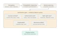
Under this architecture, a fundamental gap emerges between two types of risk:
- Hardware/software malfunction (Functional Safety—IEC 61508). Did a relay fail or software freeze?
- Algorithmic insufficiency (SOTIF—ISO 21448). Did the algorithm act correctly according to its neural network weights, yet fail because it read the wrong environmental context, relied on an outdated CAD model or made an invalid operational assumption? This distinction is not new to the automotive domain—and industrial and physical AI now inherit it. Practitioners in heavy machinery and manufacturing automation are already carrying SOTIF analysis over.
Because downstream hardware—such as motor drives, PLCs and servo actuators—can execute commands flawlessly while the upstream reasoning remains fundamentally flawed, verification must shift from merely checking software outputs to validating the complete evidence stack behind autonomous decisions.
READ MORE: AI Gains Physical Intelligence and Transforms Robotics & Automation Design
The standards world is already moving in this direction. The 2025 revision of ISO 10218—the first major update to the flagship industrial robot safety standard since 2011, adopted in the U.S. as ANSI/A3 R15.06-2025—makes functional safety requirements explicit rather than implied, and adds cybersecurity requirements to robot safety for the first time. Explicit evidence, not implied assurance, is the direction of travel.
The Actuation Boundary
Think about the exact millisecond before a robotic arm moves, or right before a high-pressure valve opens. That's the Actuation Boundary. It is the critical line where an AI’s statistical “best guess” turns into real, physical movement. We can’t treat this like a standard software update because a robot can execute a command flawlessly. But if the reasoning behind it was based on an outdated CAD file, the result is still a pile of ruined inventory.
The “Evidence Before Motion” Framework
To ensure that autonomous operations meet traditional engineering standards, systems should address five core questions before crossing the Actuation Boundary:
- Context Check: Am I operating on the latest hardware build, spatial map and engineering context?
- Authorization Check: Do I have active authorization to alter this specific parameter or cross this boundary right now?
- Safety Check: Are all physical safety constraints and ISO 3691-4 interlocks active and satisfied?
- Explainability Check: Is the logic behind my chosen action human-readable and traceable?
- Reconstructibility Check: Is my current state, input and telemetry logged for future UL 4600 audit replay?
Answering these five questions shifts system design from a confidence-first AI workflow (relying purely on statistical probability scores) to an evidence-first engineering workflow.
The Engineering Evidence Stack & Regulatory Alignment
To answer these questions in real time, autonomous control architectures should implement an Engineering Evidence Stack that validates data layer-by-layer prior to physical execution:
|
Layer |
Focus & Role |
Applicable Engineering & Safety Standards |
|
6. Physical Execution |
Deterministic motor, valve, or relay actuation |
ISO 10218:2025 (Robotics), ISO 3691-4 (AMRs/AGVs) |
|
5. Reasoning Evidence |
Traceable logic chain and confidence bounds supporting the proposed action |
UL 4600-style safety-case transparency |
|
4. Safety Validation |
Independent interlock checks, speed limits and keep-out zone verification |
IEC 61508 (SIL Ratings), ISO 13849 (Performance Levels) |
|
3. Policy & Authorization |
Operational permissions, role-based access and command boundaries |
IEC 62443 (Industrial Cybersecurity) |
|
2. Operational Context |
Fresh sensor telemetry, machine state and environmental conditions |
ISO 21448 (SOTIF / Triggering Conditions) |
|
1. Engineering Context |
Version-controlled CAD revisions, process specifications and schematics |
ISO 9001 document control / configuration management |
The Engineering Evidence Stack extends a vendor-independent reference architecture for verifiable AI context that I have specified in an open-access preprint, applied here to the actuation boundary.
Practical Manufacturing Examples: When Reasoning Fails
The necessity of an evidence trail becomes obvious when evaluating subtle failure modes in automated industrial environments.
Case 1: The robotic welding cell. Imagine an industrial welding arm running on an outdated CAD file. It glides with millimeter precision, following its programmed path flawlessly. But because the underlying blueprint was old, every single weld line is off by a fraction of an inch—turning expensive raw material into pure scrap. Flawless physical execution, broken engineering context.
Case 2: The autonomous forklift. Picture a self-driving forklift gliding down warehouse aisles, effortlessly dodging workers and adhering strictly to ISO safety protocols. It performs perfectly—except it picks up the wrong pallet because the inventory database was stale. Successful motion control, failed operational reasoning.
In both scenarios, the engineering failure occurred before physical motion took place, proving that software confidence alone cannot guarantee process correctness.
Engineering Design Checklist
When designing or integrating physical AI systems, control teams should enforce the following design checklist:
- Version-controlled engineering context. Automatically bind decision logs to active CAD, firmware, and software revisions, linking generated motion profiles directly back to source engineering artifacts.
- Verified telemetry freshness. Validate sensor timestamps to prevent decisions based on latent or frozen data feeds (addressing SOTIF risks per ISO 21448).
- Policy and authorization checks. Verify permissions dynamically before command execution.
- Hardware-enforced safety validation. Ensure deterministic safety PLCs or hardwired interlocks (IEC 61508 / ISO 13849) sit downstream of AI logic.
- Deterministic human override. Maintain physical e-stops or manual takeover paths that immediately bypass AI control loops.
- Complete action reconstructability. Archive input state vectors to support UL 4600-style safety-case audits.
Conclusion: Evidence Before Motion
Physical AI marks a transformative evolution in industrial automation, expanding machine capabilities beyond rigid, pre-programmed routines. However, autonomy alone cannot earn engineering trust.
READ MORE: Physical AI Hype vs Reality: Kung Fu Robots are Cool...But Should You Hire One?
Every classical engineering field depends on verifiable evidence to enable independent auditing, accident investigation and continuous quality control. Autonomous physical systems must be held to this exact standard. As AI continues to assume control over physical machinery and industrial operations, engineering evidence—not AI confidence—must determine whether a decision is granted permission to cross the Actuation Boundary.
"Evidence before motion" must become a non-negotiable principle for the next generation of physical AI.
References:
- ISO 21448:2022 (SOTIF)
- SOTIF carry-over to manufacturing automation
- ANSI/UL 4600 Ed. 3 (2023), Evaluation of Autonomous Products
- ISO 10218-1:2025
- ISO 10218-2:2025
- ISO 10218:2025 revision summary (A3 FAQ)
- ANSI/A3 R15.06-2025 adoption
- ISO 3691-4 (driverless industrial trucks and their systems) — International Organization for Standardization
- ANSI/A3 R15.08 (industrial mobile robot safety) — Association for Advancing Automation
- IEC 61508 series (functional safety) — International Electrotechnical Commission
- ISO 13849-1 (safety of machinery, performance levels) — International Organization for Standardization
- IEC 62443 series (industrial cybersecurity) — International Electrotechnical Commission
- NVIDIA Physical AI definition
- Vibhuraja Bhutani, "The Verifiable Context Layer" (open-access preprint)
More content from Takeover Week: Automation & Robotics.
About the Author
Vibhuraja Bhutani
VP of Products & Business Strategy, Softweb Solutions
Vibhuraja (Vibhu) Bhutani is VP of Products & Business Strategy at Softweb Solutions, an Avnet company, where he has spent 13 years building enterprise IoT and edge AI platforms for manufacturing. He is the author of “The Verifiable Context Layer.” an open-access reference architecture for verifiable AI.
Voice Your Opinion!
To join the conversation, and become an exclusive member of Machine Design, create an account today!
 Leaders Logo
Leaders relevant to this article: