6 Reasons Cable Size and Management Are Critical for Modern Robotics
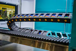
As robots become smaller and faster, cable sizing and routing play a greater role in machine reliability. Proper bundle sizing, protective sleeving and motion planning help prevent overheating and mechanical interference.
1. Miniaturized Robots Leave No Margin for Cable Error
Industrial robotics supports a growing installed base of manufacturing equipment. The International Federation of Robotics reported 542,000 industrial robot installations worldwide in 2024, while the operational stock reached 4,664,000 units—an increase of 9% year over year.
The trend toward smaller, lighter robots adds pressure to internal cable design. Collaborative robots, compact manipulators and lightweight end-effectors leave less room for conductors, connectors, strain relief and protective structures.
Reducing cable dimensions requires careful evaluation of current-carrying capacity, insulation, shielding and minimum bend radius. Engineers must establish the smallest practical harness envelope while meeting electrical and mechanical requirements.
READ MORE: Robotics Readiness Checklist: 6 Things to Ask Before Implementation
Measurements should reflect the complete assembly, including branches, connectors, sleeves and mounting features. Designers should evaluate clearances throughout the full required motion and consider manufacturing tolerances, cable displacement and orientation changes.
2. Torsional Motion Demands Different Cable Engineering
Cable durability depends on the forces generated by its movement, affecting conductors, insulation, shielding and outer jackets differently. Cable selection must reflect the robot’s actual motion profile, including joint rotation and travel distance.
Drag Chains vs. Robot Joints
Drag chains guide cables through a defined bend radius along a controlled path. Robot joints introduce additional demands, including alternating torsion and bending. These forces become especially pronounced when a cable crosses multiple moving axes.
A cable rated for millions of drag-chain cycles can still fail prematurely in an industrial robot. Torsion may displace internal conductor bundles or distort shielding. Excessive tension transfers loads to connectors, while repeated contact with carrier edges accelerates jacket abrasion.
Engineers should verify ratings for continuous flexing and torsion separately. Manufacturer specifications should identify the permitted bend radius, twist angle, cycle conditions and environmental limits. Cable construction must suit the expected movement, with the routing system providing the necessary clearance and freedom of motion.
Modeling Cable Stress at Critical Robot Poses
Simulation helps engineers locate potential failure points before building a physical harness. Critical poses include joint angle combinations that produce significant twist, bend radius, cable extension or minimal clearance from surrounding components.
A peer-reviewed study examined cable path optimization for industrial robot arms. Its methodology evaluated cable geometry under static conditions at critical poses and during dynamic motion, helping engineers assess stress constraints and reduce design iteration time.
READ MORE: Prioritizing Human Safety in Industrial Robot Design
Engineers can use simulation to compare routing configurations before committing to a harness design. Models should account for cable length, guide locations, attachment points and minimum bend radius. Physical testing is still necessary to validate friction, cable displacement and behavior under actual operating conditions.
3. Precise Outer Diameter Calculations Prevent Mechanical Binding
Bundle OD determines the space required for protective sleeving, cable carriers, internal passages and mounting hardware. An underestimated diameter can force cables into restricted spaces and increase pressure, while an oversized estimate may require larger carriers and consume space for other components.
Measuring Bundle Diameter and Determining Fit
A practical sizing process starts with the actual cable arrangement and the intended protective sleeve:
- Measure the complete bundle. Use calipers to check the assembled cables at several points, including branches and changes in packing density. Avoid compressing the bundle, which can produce an artificially small measurement.
- Account for tolerance. Consider variations in cable diameter and packing arrangement. For irregular bundles, measure the largest cross-sectional dimension rather than relying on an average.
- Choose the sleeve fit. Compare the measured outer diameter (OD) with the sleeving manufacturer’s expansion range and installation guidance.
- Check installed clearance. Ensure the sleeved assembly clears joint housings, carrier walls and nearby components throughout the robot’s full range of motion.
Expandable braided sleeving needs an additional length calculation. As the braid expands in diameter, it generally becomes shorter. Engineers should allow extra material when cutting the sleeve so it reaches its attachment points without pulling taut.
Selecting Protective Sleeving by Temperature Rating
Sleeving must withstand the heat and mechanical demands of its installation. A material may resist abrasion while breaking down under high temperatures. Engineers should also consider flexibility, chemical compatibility and installation requirements. Here are temperature ratings for three standard sleeving materials:
- Polyethylene terephthalate. Up to 125°C or 257°F.
- Polyphenylene sulfide. Up to 150°C or 302°F.
- Perfluoroalkoxy. Up to 260°C or 500°F.
These ratings provide a starting point for material selection, but engineers should still confirm the rating for the exact product and consider whether it applies to a particular application.
4. Dense Harness Packing Creates Thermal Hot Spots
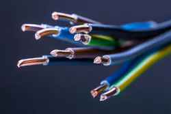
Tightly packed cables can trap heat, especially when several conductors carry current inside a sleeve with limited airflow. Temperature rise depends on current, conductor resistance, insulation and bundle density. Some industrial inspection robots operate in environments exceeding 200°F and use thermal imaging to detect temperature differences as small as 0.1°F.
Engineers should assess heat under typical operating conditions and select sleeving that meets temperature requirements. Testing can reveal hot spots and help determine whether to increase cable spacing, reduce bundle density or reroute cables away from heat sources.
5. Cable Binding Leads to Damage
Cable binding occurs when a harness cannot move freely with the robot. An overfilled carrier, insufficient slack or poor strain relief can cause cables to rub against walls or pull on connectors. A route that works in the home position may restrict movement as joints rotate.
Interference can damage cables, disrupt motion or create snagging hazards. OSHA identifies power cables and hoses as potential tripping and falling hazards in industrial robot workplaces. Engineers should inspect the full cable path for pinch points and loose loops. Testing the robot across its full range of motion can reveal deformation before deployment.
6. Poor Harness Design Accelerates Conductor Fatigue
Repeated bending, twisting, tension and vibration can damage conductors and shielding, even when the outer jacket appears intact. Tight bend radii and excessive bundle compression increase stress on vulnerable sections.
READ MORE: Q&A with the Robot Guy: David Sandiland Discusses Robotics Cable Management
Accurate bundle OD measurements, suitable sleeving and careful routing help preserve clearance and reduce abrasion. Engineers should combine simulation with physical cycle testing to identify wear, monitor high-stress areas and check thermal performance.
Maintenance intervals should reflect the robot’s duty cycle and operating environment. Tracking wear patterns and replacement history can also guide improvements to future harness designs.
Precision Cable Design Prevents Costly Downtime
Reliable robotic cable management starts with accurate measurements and careful routing. By accounting for heat, stress and clearance throughout the robot’s range of motion, engineers can reduce cable wear and extend equipment life.
About the Author
 Emily Newton
Emily Newton is a technology and industrial journalist. She is also the editor in chief of Revolutionized. She has over five years covering stories about warehousing, logistics and distribution.


Voice Your Opinion!
To join the conversation, and become an exclusive member of Machine Design, create an account today!
 Leaders Logo
Leaders relevant to this article: